Well 36dB, but master or slave I do not know, I think slave, but I always think slave 🙂
If Fluke tells you 400khz it is master 🙂
Is it R22 and R23 that give the gain?
Master/Slave: what happens when you try to drive a slave from a slave? A mess?
Since I have 4 amps working together should I be thinking of master/slave config? This sort of explains a strange thing that happened on power up. One of the woofers started moving very slowly but deep through full stroke - almost like a 4Hz or so beat frequency because not locked together?
It hasn't happened again.
Last edited:
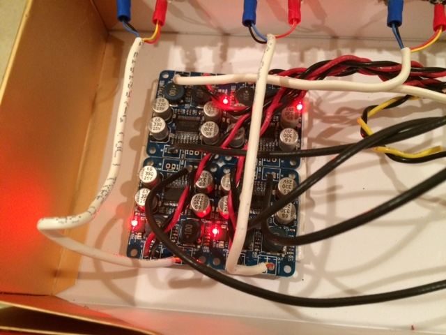
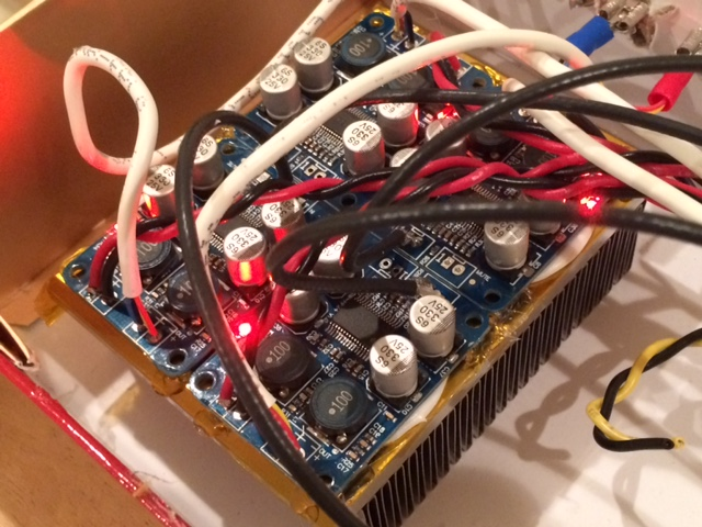
Well it took me a bit longer than tomorrow to hook them up...
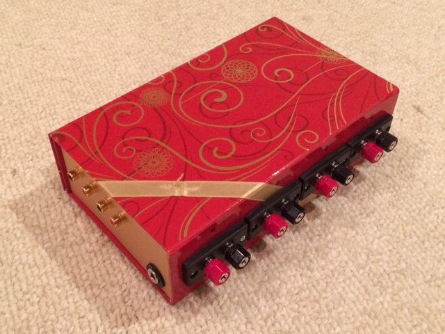
I put all four monoblocks into a case for a 4 channel active amp to be used with a miniDSP. The case is a cardboard Xmas chocolate box with magnetic snap lid, hence I will call this the "Xmas Amp". I am using RG-174 coax from RCA's to the amp, 18 ga stranded wires for power, and doubled-up solid core 22 ga copper for connection from amp out to binding posts. For output connection, I have some nice 5-way banana binding posts, and 4x RCA inputs, and room inside the box leftover for the miniDSP later.
Here are some photos. The amp even has an SMT red LED power on indicator.
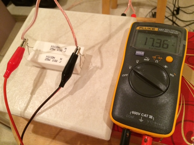
I hooked up a 5ohm 50w dummy load resistor, used a 24v SMPS, and clocked 17.36 volts as measured with a Fluke 101. The resistors were smokin' hot and outgassing something serious stinky smells (I could not touch them), the amp chip was hot and not comfortable to touch, the inductors (surprise), were barely warm. I ran for 5 minutes with 1kHz and the thermal shutoff never tripped. So it's a bonafide 60w into 5ohm amp.
I listened to it and was *REALLY* pleasantly surprised. In stock form, it sounds excellent. Great bass authority driving my 6.5in woofers in a 2-way (GR Research XL-S). Highs are clear and with good resolution and transparency. Ran through about 10 of my typical test tracks and they all sound good.
In summary, this amp is an excellent value, sounds great and is tiny. I highly recommend it.
xrk,
Looks delicious and very festive🙂. Thank you for the brief review. I'll get a pair to try it out. However, have to figure out a way to help the cooling. Do not want to heat up all the components unnecessarily.
Regards,
Is it R22 and R23 that give the gain?
Master/Slave: what happens when you try to drive a slave from a slave? A mess?
Since I have 4 amps working together should I be thinking of master/slave config? This sort of explains a strange thing that happened on power up. One of the woofers started moving very slowly but deep through full stroke - almost like a 4Hz or so beat frequency because not locked together?
It hasn't happened again.
xrk,
If you do not sync the chips together, it should be OK? If you sync them, then you have set one of them the master and the other 3 slaves by changing the resistors. My 2 cents.
No not r22/r23, c26 is gvdd, r27/r28 connections to gvdd aren't visable to me, so again Fluke can tell how C26 is connected to any of these resistors, I thought it may be connected at chipside, directly, no divider and then it might be slave, but really just guessing.
Lo_Tse,
I think RTV silicone the amps to an aluminum panel or a small heat sink block with fins should be fine - it just needs to pull off 6 watts ea. I will do this myself and report back on efficacy of heat transfer and cooling.
I may steal a nice finned heat sink from one of my TDA7498's for this very purpose.

That black finned heat sink is the perfect size and probably more than enough heat removal.
have to figure out a way to help the cooling. Do not want to heat up all the components unnecessarily.
I think RTV silicone the amps to an aluminum panel or a small heat sink block with fins should be fine - it just needs to pull off 6 watts ea. I will do this myself and report back on efficacy of heat transfer and cooling.
I may steal a nice finned heat sink from one of my TDA7498's for this very purpose.
That black finned heat sink is the perfect size and probably more than enough heat removal.
Lo_Tse,
I think RTV silicone the amps to an aluminum panel or a small heat sink block with fins should be fine - it just needs to pull off 6 watts ea. I will do this myself and report back on efficacy of heat transfer and cooling.
I may steal a nice finned heat sink from one of my TDA7498's for this very purpose.
That black finned heat sink is the perfect size and probably more than enough heat removal.
xrk,
You just gave me an idea!! Your picture reminded me of the 2 blown Audiobah green boards that I still have. I am going to use their heat sinks for these little guys😀 Thanks!
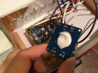
Xmas amp with heat sink
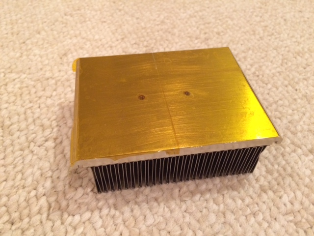
I happened to have a really nice solid copper Pentium CPU heat sink lying around. It is the perfect size match for the footprint of 4 of these Sanwu Blue PBTL amps. I put down a layer of Kapton tape to prevent shorts from solder pins on the bottom. Then added a dollup of RTV silicone. Pressed it in place on heatsink to squash the RTV flat and reduce thickness for higher heat transfer efficiency. Used a few dabs of hot melt glue on corners of PCB and heatsink to hold PCB in place while RTV silicone cures. The final completed amps mounted on this heatsink is way overkill (I think a 1/8in aluminum plate would have worked just fine. I just happened to have this heatsink and it looks cool.
Kapton tape cover:
Apply RTV silicone:

Completed amp with heatsink - almost looks like it was designed for it:
I then put the amp through the stress test using the 5ohm dummy load (50w power resistor). I connected the CD player as source this time rather 1kHz signal generator. I played some music at full volume on the headphone outs of the CD player and fed to the amp input. I measured between 17v and 19.5v on the load resistor and let it play for 5 minutes each again. The resistors got smoking hot, even the ceramic tile they were on was too hot to touch near where the resistors were placed. My fingertip touch test on the amp chip itself showed significantly lower temperature as I could leave my finger on the chip and it felt warm but not hot. I discovered that these amps generate sound - probably piezoelectric effect of all those ceramic caps. You can hear faint music playing from the amp board as all I had was the dummy load. Anyhow the amps were clocking in between 60w and 75w and could run all day with this heat sink I think.
I happened to have a really nice solid copper Pentium CPU heat sink lying around. It is the perfect size match for the footprint of 4 of these Sanwu Blue PBTL amps. I put down a layer of Kapton tape to prevent shorts from solder pins on the bottom. Then added a dollup of RTV silicone. Pressed it in place on heatsink to squash the RTV flat and reduce thickness for higher heat transfer efficiency. Used a few dabs of hot melt glue on corners of PCB and heatsink to hold PCB in place while RTV silicone cures. The final completed amps mounted on this heatsink is way overkill (I think a 1/8in aluminum plate would have worked just fine. I just happened to have this heatsink and it looks cool.
Kapton tape cover:
Apply RTV silicone:
Completed amp with heatsink - almost looks like it was designed for it:
I then put the amp through the stress test using the 5ohm dummy load (50w power resistor). I connected the CD player as source this time rather 1kHz signal generator. I played some music at full volume on the headphone outs of the CD player and fed to the amp input. I measured between 17v and 19.5v on the load resistor and let it play for 5 minutes each again. The resistors got smoking hot, even the ceramic tile they were on was too hot to touch near where the resistors were placed. My fingertip touch test on the amp chip itself showed significantly lower temperature as I could leave my finger on the chip and it felt warm but not hot. I discovered that these amps generate sound - probably piezoelectric effect of all those ceramic caps. You can hear faint music playing from the amp board as all I had was the dummy load. Anyhow the amps were clocking in between 60w and 75w and could run all day with this heat sink I think.
Attachments


No not r22/r23, c26 is gvdd, r27/r28 connections to gvdd aren't visable to me, so again Fluke can tell how C26 is connected to any of these resistors, I thought it may be connected at chipside, directly, no divider and then it might be slave, but really just guessing.
The fluke shows 400kHz (with slight differences on each since each is its own master). It measured something like 399.9kHz, 400.3kHz, 400.1kHz, 399.7kHz.
Nice it is master. Why all the heatsinking? You are going to use them to bassEQ small speakers?
It's going to be my new portable 60w/ch active miniDSP rig. I want to have the head room to play loud transients. As it was before it felt too hot for sustained 60w. I also just happened to have this heatsink so it was handy.
That's a great price! I have a feeling the Sanwu Blue is going to become a new favorite around here.
Technically we should discuss in 3118 thread.
Technically we should discuss in 3118 thread.
Sanwu Blue PBTL amp discussion in TPA3118D2 thread:
http://www.diyaudio.com/forums/class-d/219730-tpa3118d2-25.html#post4585203
http://www.diyaudio.com/forums/class-d/219730-tpa3118d2-25.html#post4585203
Hi,
I'm new to the TPA3116 crave..LOL...thanks to xrk971 for many PM in guiding me in the right direction.
I'm about to purchase the YJ Green board that seem to be a copy of the Audiobah PCB but at 1/2 the price.
YJ Green : YJ Assembled TPA3116 Class D Amplifier Board 50W 50W Green PCB | eBay
Audiobah : Amplifier Board TPA3116 Class D 2X50W The Only with Speaker Protection | eBay
Why is the Audiobah double the price compare to the YJ Green PCB ?
What I want is a free turn on/off pop amplifier, I want to avoid having to add a speaker switch, mute switch or external delay with capacitor, etc.
Thanks for your help.
Eric
Last edited:
If YJ green does not have turn on/off pop it should be fine. Audiobah is smaller company and can't compete with mass production volume of YJ Juggernaut. The caps on YJ are typically marginal so maybe plan on spending a few $ for nice Panasonic FM's or OSCONs.
I would personally try cheaper YJ first. If you are going to spend $30 on a PCB consider spending a few more on excellent boxed SMSL whixh also has no pop.
I would personally try cheaper YJ first. If you are going to spend $30 on a PCB consider spending a few more on excellent boxed SMSL whixh also has no pop.
Hi,
I tried last night a YJ red pcb like shown below. Sound is good but my efficiency full range (96db) almost vanished in smoke with the huge turn-on pop.
YJ red : New TPA3116 Class D 50W 50W Filter Capacitor 25V 2×1000UF Power Amplifier Board | eBay
The YJ green is not $30, it's only $15.
BR,
Eric
I tried last night a YJ red pcb like shown below. Sound is good but my efficiency full range (96db) almost vanished in smoke with the huge turn-on pop.
YJ red : New TPA3116 Class D 50W 50W Filter Capacitor 25V 2×1000UF Power Amplifier Board | eBay
The YJ green is not $30, it's only $15.
BR,
Eric
That's what I meant - get the YJ Green Audiobah clone. Yes, 96dB speakers don't take kindly to thump. Although many pro drivers have a large xdamage figure are quite safe. It's disconcerting to hear that's for sure. Maybe you are more worried about your compression drivers?
I see a transistor on the YJ green and assume that is part of ten anti thump circuit.
I see a transistor on the YJ green and assume that is part of ten anti thump circuit.
How thick is the silicone layer between the board and the heatsink? From the pictures seen the thermal paths resistance is pretty much "not optimal". 😀
Nice build anyway.
Nice build anyway.
That's what I meant - get the YJ Green Audiobah clone. Yes, 96dB speakers don't take kindly to thump. Although many pro drivers have a large xdamage figure are quite safe. It's disconcerting to hear that's for sure. Maybe you are more worried about your compression drivers?
I see a transistor on the YJ green and assume that is part of ten anti thump circuit.
Thanks, I just bought the YJ Green Audiobah clone.
My drivers are Fostex FE206E so not compression drivers. They have survive the thump but my heart skipped a beat...LOL
Thanks for everything,
BR
Eric
I squashed the board down as much as possible so that's why so much oozed out. The thickness is probanly 1mm to 1.5mm. I know it's not optimal but it's better than relying on tiny bare board to act as heat sink. It does not have capability to dissipate 10% of 60w or 6w very well without this RTV to heatsink. The heatsink can be felt to be warm to the touch when amps are running at moderate power so heat transfer is occurring.
I had a thought and maybe just soldering a copper disc stub to the chip vias on the bottom and the connecting that to a conventional aluminum plate heat sink. The nice thing with RTV on entire board is that it helps remove heat from inductors too.
I had a thought and maybe just soldering a copper disc stub to the chip vias on the bottom and the connecting that to a conventional aluminum plate heat sink. The nice thing with RTV on entire board is that it helps remove heat from inductors too.
- Home
- Amplifiers
- Class D
- TPA3116D2 Amp