Just get in from shop. Give me about 20 mins and I'll post a PIC of my tlspice circuit.
To be honest, I didn't understand the equations in the link I last posed from the embedded site.
To be honest, I didn't understand the equations in the link I last posed from the embedded site.
Hmm ok sorry if i seem like a big dummy but when doing the Zobel network is it also necessary to know the impedance profile of the speakers that will be hooked up? Seems to me if all that can be brought to the right calculations then we might really really have something special in creating an active speaker.
Don't think that's necessary in any perfection of values, as its calculations should be based on the LC circuit. The zobel in the output circuit does however base its calculation on speaker+cables if you are optimising it.
That makes me wonder if the "matching output zobel to speakers" post/thread which was mentioned for any board, will also work out the values!!
Didn't get to post LTspice circuit and graphs as I didn't save the file. Spent couple of hours redrawing the output filter on back of my crossover file and even before adding the Boucherot cell circuit something wasn't right. I tracked down a couple connctions not made properly, still not same as before. Not sure if I connected the output circuit to the pllxo circuit differently before, missed a ground or put one where I shouldn't. Just couldn't find problem. The only thing I can think of now is I may have worked on different xo values which I didn't save before trying the output with it. That wouldn't surprise me, as I did change it about before trying the output.
Didn't want to try the Boucherot cell and post if I didn't get it as it was when I tested before, as even before I put it in the graph didn't match what I have explained in previous post.
I'll give another go in morning.
I am not sure how to model this in Spice - do I pick opposing phase voltage drive sources for the amp pins?
Stanley, if you want to take a crack at suggesting what values to use that would be helpful.
The idea is that it needs to damp AC oscillations between the total dual LC *system" impedance as presented to the speaker driver as both sides are used. 22R or 10R, all the same...
Really not sure how to suggest the spice circuit for a regular speaker crossover as I used pllxo.
I basically drew my pllxo with the output of source splitting into balanced before passive parts. This then passed through decoupling cap, then 30k resistor (26db gain),then decoupling cap in neg line on both channels, creating 2 balanced inputs, each with a 30k resistor as the IC. The neg output of the crossovers join the neg lines after decoupling cap, and the 2 lines have to become 1 to enter return of signal source. Only placed 1 GND in crossover at the neg side of source where circuit reentered.
Don't know if putting regular speaker xo like this would have same effect.
From there on it was the output filters,which I swear I had connected by just attaching either side of the channel between the decoupling cap and resistor. But as I say, I wasn't getting same graph. The connection may have been the problem, actually it may have been the output filter GND passing to signal pllxo GND. Maybe I didn't have a GND on signal neg side once output circuit in place.....but that's a tangent!!!
Values? There's a tricky one. Info suggests it will depend on the Inductor used. I really believe it doesn't have anything to do with the speaker here. It will be the component model of the inductor used as that's the coil its working with. So for the two inductors gets a little more tricky but must be total of both. I believe the voice coil model is RLLCR.
R evc is the Voice Coil DC resistance
L evc is the Voice Coil Inductance
L ces is the electrical analog of driver mechanical suspension compliance
C mes is the electrical analog of driver mechanical cone mass R es is the electrical analog of driver mechanical suspension resistance
As far as I can tell, R= coil dc resistance measured in Ohms with multimeter (how to account for both???). And Cap is coil inductance (measured with inductance meter ot from manufacturers specs ÷ coil DC resistance (again how to account for both?)
Ringing on BlueBlack Board Supply lines
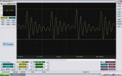
Hi, I have some observations on the old Blue Black Board. I was poking around before starting the recommended set of mods and I noticed that stock board has severe ringing on the supply lines ( around 300mV ). The ringing happens in sync with switching on the Out pins. I was using a transformer based supply to ensure that the switching noise did not come from the supply itself.
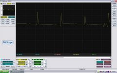
I expected that replacing the stock PS Jamecon caps with Oscons would fix the problem but it did not. The ringing reduced but it did not go away. That's the second waveform. It was only after I removed the 100nF ceramic SMD bypass caps that the ringing stopped (3rd Pic) I ended up replacing all the ceramic bypass caps with 1uF 25V 0805 SMDs from TDK and that gave me the least noise on the supply lines ( around 63mV in the 4th pic).
The funny thing is that I never realised that there was a problem when I listened to music on the stock board. But once I did the changes it sounded smoother . I'm not sure if this issue is there on other boards but it might be worth checking.
Cheers,
Santhosh
Hi, I have some observations on the old Blue Black Board. I was poking around before starting the recommended set of mods and I noticed that stock board has severe ringing on the supply lines ( around 300mV ). The ringing happens in sync with switching on the Out pins. I was using a transformer based supply to ensure that the switching noise did not come from the supply itself.
I expected that replacing the stock PS Jamecon caps with Oscons would fix the problem but it did not. The ringing reduced but it did not go away. That's the second waveform. It was only after I removed the 100nF ceramic SMD bypass caps that the ringing stopped (3rd Pic) I ended up replacing all the ceramic bypass caps with 1uF 25V 0805 SMDs from TDK and that gave me the least noise on the supply lines ( around 63mV in the 4th pic).
The funny thing is that I never realised that there was a problem when I listened to music on the stock board. But once I did the changes it sounded smoother . I'm not sure if this issue is there on other boards but it might be worth checking.
Cheers,
Santhosh
Attachments

Hi, I have some observations on the old Blue Black Board. I was poking around before starting the recommended set of mods and I noticed that stock board has severe ringing on the supply lines ( around 300mV ). The ringing happens in sync with switching on the Out pins. I was using a transformer based supply to ensure that the switching noise did not come from the supply itself.
I expected that replacing the stock PS Jamecon caps with Oscons would fix the problem but it did not. The ringing reduced but it did not go away. That's the second waveform. It was only after I removed the 100nF ceramic SMD bypass caps that the ringing stopped (3rd Pic) I ended up replacing all the ceramic bypass caps with 1uF 25V 0805 SMDs from TDK and that gave me the least noise on the supply lines ( around 63mV in the 4th pic).
The funny thing is that I never realised that there was a problem when I listened to music on the stock board. But once I did the changes it sounded smoother . I'm not sure if this issue is there on other boards but it might be worth checking.
Cheers,
Santhosh
Nice work! Thanks for pointing this out. I wonder if this is the cause of why the YJ Blue Black board runs warm compared to other boards I have used. The inductors are warmer as well as the main chip heatsink. The Ybdz Wiener board for example is always essentially cold to the touch. I wonder if this is the reason why replacing the bootstrap caps with high quality ceramic ones has been shown to improve the sound, along with the bootstrap snubber mod - all of these seem to be aimed at reducing the ringing from the switching transients. Never thought to look at the power supply input as means to probe the ringing.
Nice work! Thanks for pointing this out. I wonder if this is the cause of why the YJ Blue Black board runs warm compared to other boards I have used. The inductors are warmer as well as the main chip heatsink. The Ybdz Wiener board for example is always essentially cold to the touch. I wonder if this is the reason why replacing the bootstrap caps with high quality ceramic ones has been shown to improve the sound, along with the bootstrap snubber mod - all of these seem to be aimed at reducing the ringing from the switching transients. Never thought to look at the power supply input as means to probe the ringing.
Actually I did the measurements across the terminals of one of the PS electrolytic caps. The waveform at the supply input to the board was pretty similar to the voltage across the electrolytics but not always the same ( some kind of parasitic effect I guess ).
I also tried checking the voltage waveform across the bootstrap caps with the oscilloscope. An ideal cap should show almost 0 volts across it as the output switches. However my scope kept freezing and I was not able to measure this. Hopefully someone with better equipment can take a look at that.
Cheers
Sant
Hi Santosh,
At which points on the board did you measure the ringing ?
Thanks.
J.
At which points on the board did you measure the ringing ?
Thanks.
J.
Hi, I have some observations on the old Blue Black Board. I was poking around before starting the recommended set of mods and I noticed that stock board has severe ringing on the supply lines ( around 300mV ). The ringing happens in sync with switching on the Out pins. I was using a transformer based supply to ensure that the switching noise did not come from the supply itself.
I expected that replacing the stock PS Jamecon caps with Oscons would fix the problem but it did not. The ringing reduced but it did not go away. That's the second waveform. It was only after I removed the 100nF ceramic SMD bypass caps that the ringing stopped (3rd Pic) I ended up replacing all the ceramic bypass caps with 1uF 25V 0805 SMDs from TDK and that gave me the least noise on the supply lines ( around 63mV in the 4th pic).
The funny thing is that I never realised that there was a problem when I listened to music on the stock board. But once I did the changes it sounded smoother . I'm not sure if this issue is there on other boards but it might be worth checking.
Cheers,
Santhosh
That was my next mod, but using leaded PP caps.
I've already swapped out the 1nf for leaded class 1 ceramics, and that definitely made a difference in sound from stock smd.
Do you think swapping out the 10nf across the +/- input would improve it more so?
This is problem with smd of extremely cheap boards. Unless you buy with full assembly list, there's no way of knowing quality and performance of fitted smd/t.
Stressing all night that I couldn't get the joined pllxo and output circuit to work last night to show effect of Boucherot cell on phase. Not the best nights sleep!
It did make me wonder though....... Boucherot cells are placed across +/- terminals of speakers,... So would placing a Boucherot cell across in and out of each individual inductor coil instead of across the 2 inputs of each channel inductor work better?? Or would this just create a bypass??
I WILL get the circuit working this morning, and try without, across both channels, and across individual inductors.
Last edited:
You could place a 100nF smd within 2.5mm maximum distance from chippins and a bigger value smd within 6mm maximum distance from chippins to improve decoupling (reduce ripple) as TI suggests for similar amlifier. Yjblue also has a problematic bootstrap distance/inductance, so all PSU decoupling YJblue is problematic. For red and green YJ/AC boards bootstrap isn't problematic imo, other PSU decoupling sometimes even worse than YJblue. Most later 3116 ampboards have better decoupling than the three oldest boards.
(TH parts to replace SMD parts for decoupling in their original pcb location only increases inductance/distance)
(TH parts to replace SMD parts for decoupling in their original pcb location only increases inductance/distance)
Stressing all night that I couldn't get the joined pllxo and output circuit to work last night to show effect of Boucherot cell on phase. Not the best nights sleep!
It did make me wonder though....... Boucherot cells are placed across +/- terminals of speakers,... So would placing a Boucherot cell across in and out of each individual inductor coil instead of across the 2 inputs of each channel inductor work better?? Or would this just create a bypass??
I WILL get the circuit working this morning, and try without, across both channels, and across individual inductors.
Still didn't get results I achieved before adding the Boucherot cell. Its either I did it before the final crossover point I have values now saved for in pllxo, or I altered how I connected the two.
Anyhow. With what I did get on TLspice was a perfectly aligned crossover, and the phase lines out of the output circuits still drifted apart, but only at top cross over point. Unfortunately none of the dB or degrees numbers match what I achieved before.
When I added the Boucherot cell across inductor inputs the effect was much less, but it did move them apart slightly to give a better 180degree separation between +/- lines above crossover frequency of 5105Hz.
Using the mod across in and outs of each inductor did nothing, which I was unsure if it would or not.
My tests have only been using after pllxo. As I heard the difference driving without crossover straight into full range woofer on both channels I'll give a spice test of that setup.
Hmm..
Sant_ka's post has prompted me to dig up my old scope.
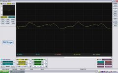
Measured across the decoupling capacitor (YJ blue black board) - it is ringing.
As soon as i clear some time, i will try bypassing it with a smaller cap.
After abit more testing... 3.3uf across the decoupling cap cleans it up. I coudnt hold the camera and the wires at the same time.
Sant_ka's post has prompted me to dig up my old scope.
Measured across the decoupling capacitor (YJ blue black board) - it is ringing.
As soon as i clear some time, i will try bypassing it with a smaller cap.
An externally hosted image should be here but it was not working when we last tested it.
After abit more testing... 3.3uf across the decoupling cap cleans it up. I coudnt hold the camera and the wires at the same time.
Last edited:
Hi Santosh,
At which points on the board did you measure the ringing ?
Thanks.
J.
Measurements were taken at the solder points of one of the PS electrolytics i.e. where the legs are soldered to the board.
Cheers
Sant
Hmm..
Sant_ka's post has prompted me to dig up my old scope.
Measured across the decoupling capacitor (YJ blue black board) - it is ringing.
As soon as i clear some time, i will try bypassing it with a smaller cap.
An externally hosted image should be here but it was not working when we last tested it.
After abit more testing... 3.3uf across the decoupling cap cleans it up. I coudnt hold the camera and the wires at the same time.
I don't mean to discourage you from trying but I tried a number of bypassing caps , ceramic, film etc etc but nothing really worked until I ripped out the 100nFs. A 2.2uF orange drop cap helped and so did a 0.1uF MMK ( from Rifa ?? )
Thanks for the heads up Sant.
I tried a few capacitors which i bought as spare input caps: Wima MKP4 2.2uf and a Vishay roederstein MKT1822 3.3uf with good results (in bypass, the 3.3uf removed all traces of ringing.).
The 1.0uf Epcos (stock YJ input cap) and a 0.33uf green cap didnt quite do the trick. I'll try some tantalums tomorrow.
J.
I don't mean to discourage you from trying but I tried a number of bypassing caps , ceramic, film etc etc but nothing really worked until I ripped out the 100nFs. A 2.2uF orange drop cap helped and so did a 0.1uF MMK ( from Rifa ?? )
Last edited:
I read in one the chip data sheets that the 2 smd needed to be minimum x100 apart in value for best effect. Maybe its just the 100nf isn't large enough for this application for best effect.
Ideally xrk would answer this.
I have set up me test circuit in spice for the Boucherot cell test. What I would like to do is show comparison graphs of circuits including REAL inductor values, and LC cap values, which you guys are already using in your great sounding 3116 boards...ideally YJ blue/black.
I need to know these:
Your LC inductor values of uh and its resistance in ohms.
Your LC capacitor value in farads.
Any changes you have made to output filter values.
Your main woofer value, at least in ohms. Ideally its inductance.
The inductance of speaker driver isn't essential to get result as Boucherot cell is looking at the inductance / resistance of LC.
This way you can judge for yourself. I haven't set my ideal LC values yet. The woofers I used are from 1978 speakers with absolutely no identification on them except "1978" in marker pen. So no chance of manufacturers data, and only multimeter which tests AC/DC/V/Ohms.
The differences are much clearer to all with my pllxo removed, and the input just a signal, which my test through amp was using mobile phone through headphone cable.
Assistance please!
Xrk971 I've just been reviewing the previous posts and realise you posted your LC values. I'll add a nominal resistance to to spice coils to show results.
The equations for Boucherot cell suggest R= coil ohms, so I'll use 10ohms.
Will do that and post graphs.
The equations for Boucherot cell suggest R= coil ohms, so I'll use 10ohms.
Will do that and post graphs.
Right. So I got 4 spice graphs sorted below.
I used the SE signal input without a crossover, going through balanced inputs. the 30kOhms represents the IC on both inputs.
The LC values are those XRK has said are his on his 4Ohm 3116 board. i.e 10uH & 680nF, I have inserted a 10 Ohm resistance to the 10uH inductor.
The output resistor represents the 4 Ohm speaker driver.
I have left the rest of the output filter vales as the 3116 datasheet.
This mimicks my intitial physical test of the 3116 board using a phone outputing to 3116 board without pllxo, although I used the stock fitted LC and outputs which obviously differ from XRK's and the datasheet. This shouldnt reflect on the graphs though, and may mean that I heard a greater improvement than XRK values show, or vice versa.
I also directly powered an 8inch full range driver from amp outputs without additional XO. mine was 6 Ohm.
Basically I have used XRK's driver Ohm, and also his LC values along with datasheet ouput values.
The reason that I inserted a 10 Ohm resistance to the LC inductor is that the Boucherot cell in this use is to control the inductor resistance, not the speaker. I chose 10 Ohms for inductor.
the equation for the Boucherot cell is
R= inductor Ohms R=10.
C= inductor H/inductor Ohms^2. 10uH/(10x10)=100nF.
In the graphs below I hope at the very least the titles of each are visable.
I have done them as:
Boucherot cell test
(this has top channel without any additional circuit, as with 3116 datasheet. The bottom channel has the addition of the Bootstrap mod, as in the 3116 EVM datasheet, and as many on here have done)
Boucherot cell test 2
(this has top channel without any additional circuit, as test 1. The bottom channel has the addition of the Boucherot cell mod I am proposing across the 2 inputs to the L of the LC filter. as with the tda7492 datasheet)
Boucherot cell test 3
(this has top channel with the Bootstrap mod as per 3116 EVM datasheet. The bottom channel has only the Boucherot cell mod as per the 7492 datasheet, with optimised values based on single 10uH/680nf LC)
Boucherot cell test 4
(this has top channel with Bootstrap mod as per 3116 EVM. the bottom channel is fitted with BOTH the Bootstrap mod AND the Boucherot cell proposed, based on the 10uH/680nf LC)
The lines on the graph are basically taken either side of the "driver" resistors in each output. And I have kept them the same on each example, so.....
V(n002) is GREEN top channel above resistor.
V(n007) is BLUE top channel below resistor.
V(n010) is RED bottom channel above resistor.
V(n013) is PINK bottom channel below resistor.
Obviously to users of spice, the "dashed" lines are the corresponding phase lines.


Am I really crazy that this is a different mod from Bootstrap snubber which improves driver response and the greater sound that delivers????
I used the SE signal input without a crossover, going through balanced inputs. the 30kOhms represents the IC on both inputs.
The LC values are those XRK has said are his on his 4Ohm 3116 board. i.e 10uH & 680nF, I have inserted a 10 Ohm resistance to the 10uH inductor.
The output resistor represents the 4 Ohm speaker driver.
I have left the rest of the output filter vales as the 3116 datasheet.
This mimicks my intitial physical test of the 3116 board using a phone outputing to 3116 board without pllxo, although I used the stock fitted LC and outputs which obviously differ from XRK's and the datasheet. This shouldnt reflect on the graphs though, and may mean that I heard a greater improvement than XRK values show, or vice versa.
I also directly powered an 8inch full range driver from amp outputs without additional XO. mine was 6 Ohm.
Basically I have used XRK's driver Ohm, and also his LC values along with datasheet ouput values.
The reason that I inserted a 10 Ohm resistance to the LC inductor is that the Boucherot cell in this use is to control the inductor resistance, not the speaker. I chose 10 Ohms for inductor.
the equation for the Boucherot cell is
R= inductor Ohms R=10.
C= inductor H/inductor Ohms^2. 10uH/(10x10)=100nF.
In the graphs below I hope at the very least the titles of each are visable.
I have done them as:
Boucherot cell test
(this has top channel without any additional circuit, as with 3116 datasheet. The bottom channel has the addition of the Bootstrap mod, as in the 3116 EVM datasheet, and as many on here have done)
Boucherot cell test 2
(this has top channel without any additional circuit, as test 1. The bottom channel has the addition of the Boucherot cell mod I am proposing across the 2 inputs to the L of the LC filter. as with the tda7492 datasheet)
Boucherot cell test 3
(this has top channel with the Bootstrap mod as per 3116 EVM datasheet. The bottom channel has only the Boucherot cell mod as per the 7492 datasheet, with optimised values based on single 10uH/680nf LC)
Boucherot cell test 4
(this has top channel with Bootstrap mod as per 3116 EVM. the bottom channel is fitted with BOTH the Bootstrap mod AND the Boucherot cell proposed, based on the 10uH/680nf LC)
The lines on the graph are basically taken either side of the "driver" resistors in each output. And I have kept them the same on each example, so.....
V(n002) is GREEN top channel above resistor.
V(n007) is BLUE top channel below resistor.
V(n010) is RED bottom channel above resistor.
V(n013) is PINK bottom channel below resistor.
Obviously to users of spice, the "dashed" lines are the corresponding phase lines.
Am I really crazy that this is a different mod from Bootstrap snubber which improves driver response and the greater sound that delivers????
- Home
- Amplifiers
- Class D
- TPA3116D2 Amp