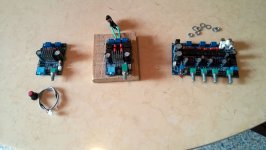
Please measure the voltage at the In+-R/L pins, they should be around 1.5Vdc and all the same. (Behind the caps)
Will do.. when I get home.
You connected 3vdc bias to your preamp/source gnd earlier. All inputs have 3vdc bias. You should be able to measure that 3vdc on new capacitors chipside. Also check the leftch both inputs are connected to gnd (PSU gnd input), if pcbtrace was damaged removing old caps the chip might not be in pbtl yet.
Tried both ampboards ? Without source connected they are quiet ?
I think normally for source to have 3vdc bias on gnd shortly isn't big problem but maybe that isn't true, source for ampboard could be damaged??? Maybe others know, you can check with other amp if used source is still ok?
Tried both ampboards ? Without source connected they are quiet ?
I think normally for source to have 3vdc bias on gnd shortly isn't big problem but maybe that isn't true, source for ampboard could be damaged??? Maybe others know, you can check with other amp if used source is still ok?
You connected 3vdc bias to your preamp/source gnd earlier. All inputs have 3vdc bias. You should be able to measure that 3vdc on new capacitors chipside. Also check the leftch both inputs are connected to gnd (PSU gnd input), if pcbtrace was damaged removing old caps the chip might not be in pbtl yet.
Tried both ampboards ? Without source connected they are quiet ?
I think normally for source to have 3vdc bias on gnd shortly isn't big problem but maybe that isn't true, source for ampboard could be damaged??? Maybe others know, you can check with other amp if used source is still ok?
I used B1 as a source at first attempt. Disconnected immediately. After checked my work, I connected only a speaker to test amp boards. After I replaced caps for both inputs and only speaker connected, distorted, scratchy sound is still there. Tried both ampboards with no source connected..
I would connect negative input now soldered to cinch chassis to psu gnd input ampboard first and if still scratchy without signal to input, check bias voltage chipside new capacitors and check gnd is connected to both leftside inputs removed caps chipside, bigcap positive trace is bottomside, smallcap negative trace is topside pcb
For measuring biasvoltage better disconnect speaker??? Can be loud
For measuring biasvoltage better disconnect speaker??? Can be loud
Checked bias voltage after the input caps.. both sides have 3vdc.. weird thing is; when i checked dc at the outputs, both sides have 9.9vdc... with and without speaker connected...
eek
both sides meaning both ampboards or meaning 3vdc measured on capless left channel? leftchannel should measure 0 if measured to psu gnd ???
both sides meaning both ampboards or meaning 3vdc measured on capless left channel? leftchannel should measure 0 if measured to psu gnd ???
Opps my bad. Only right channel.. left channel already grounded... What about dc at the outputs?
you measured 10Vdc between speaker outputs? Or between the positive speaker output and PSU gnd and the negative speaker output and PSU gnd ? That would be possible I guess
Yep. Measured positive output and psu ground and negative output and ground. Is this normal?you measured 10Vdc between speaker outputs? Or between the positive speaker output and PSU gnd and the negative speaker output and PSU gnd ? That would be possible I guess
Yes that can be normal.
(took a 14v supply and a pbtl just now on computer desk, just board+psu, on speaker output +&- 1.8mv, each output to psu gnd 7.00V)
(took a 14v supply and a pbtl just now on computer desk, just board+psu, on speaker output +&- 1.8mv, each output to psu gnd 7.00V)
Last edited:
the 10V yes🙂 scratchy sound with no input I think not. but when I tried to put gnd for negative input at my source, I had increased noises, varying frequencies, not constant volumelevel, I called it whistle like knowing it wasn't like a whistle but not knowing english word to describe it, nor good word in my own language btw🙂 you might call it scratchy??? with negative inputcaps I would try music again too
with negative inputcaps I would try music again too
I will check this tonight.. I hope I didn't damaged both boards 😉
the 10V yes🙂 scratchy sound with no input I think not. but when I tried to put gnd for negative input at my source, I had increased noises, varying frequencies, not constant volumelevel, I called it whistle like knowing it wasn't like a whistle but not knowing english word to describe it, nor good word in my own language btw🙂 you might call it scratchy??? with negative inputcaps I would try music again too
I have experienced some noise on the 3116's when the inputs were open...not connected to anything.
Gain reduction
Is it possible to chance gain with this board (default is 36dB):
New TPA3116D2 2.1 HIFI digital subwoofer amplifier Verst board 12v 50Wx2+100W
Is it possible to chance gain with this board (default is 36dB):
New TPA3116D2 2.1 HIFI digital subwoofer amplifier Verst board 12v 50Wx2+100W
Yes external part of gainsetting are two resistors per 3116 chip. After removing heatsink you would find 75k and 47k on masterchip and 16k and 100k on slavechip for 36dB gainsetting (or comparable dividers). Previously we saw pictures in this thread for a 32dB model of this pcb, that seemed to me to show stereoamp was in fact slave, bass amp master, synch partsorder suggested this was reversed, maybe accidental, original synch parts not able to function, slave amp basicly without masterclock and measured around 100khz switchingfrequency previously by others, possibly not constant switchingfrequency. Because resistorvalues for 36dB master/slave differ, you could clearly see whether stereo is master or bass is master on your pcb🙂
- Home
- Amplifiers
- Class D
- TPA3116D2 Amp
