Perhaps just the first part of 'aural' observation. 🙂 But then you have to address 'expectation bias'. That's not so easy to walk away from. I think it alone plays a huge part in what we hear - or better yet, what we WANT to hear after we make a mod.
Unlike say, medicine that is not an exact science, electronics is. Math and physics for the most part. Math and the physical makeup of the components make audio predictable IMO. Component A will have the exact same effect, if placed in the exact same circuit. Emphasis on exact. What anyone 'believes' the affect will be is of little value to the predictable results that science knows it will have. Measurements matter. And further more, the 'chain of custody' of the originating signal must not be tampered with in any way, if you're trying to perform some level of scientific evaluation on the affects your mod just made. Same source, same cable, same speakers, same everything except the mods. I would prefer to make measurements before and after and compare the results on paper, to what you think/did hear after the mod.
I think it's harder and rarer than most people are willing to admit. 😀
Absolutely. But unless you follow a proper procedure, all you'll know is that you think it sounds better. Maybe. 🙂
gmarsh, I did mention that what I was reporting was my personal experience and not a scientific experiment. I have used many different types of coupling capacitors in various positions in various pieces of hi-fi equipment and have yet to find one that does not have a "sonic signature". If they have a "sonic signature", they cannot be neutral or transparent. In contrast to that, I have found that, in my particular case, the Edcor coupling transformer under discussion was RELATIVELY far more neutral and transparent in the same application. I should not make a blanket statement that a transformer will always be better than a capacitor, and if my post appeared to say that, then I take it back, but I do believe that, unless there is a serious amount of DC in the application, the transformer will be better, hence my suggestion that the poster of the question should give it a try and report back - especially since he already has the transformer at hand.
Hey there,
some time ago I bought the DUG board. I now could find the time to order all the parts and assemble the board.
Unfortunately I cannot get sound ouf that amp 🙁.
When I power the board with 12V nothing happens and nearly no current is flowing. The Power pins all get 12V, AVCC is tied to PVCC with a 0R resistor and SDZ is at 10.9V. Sync pin is not toggling and there is 0V at GVDD. Nothing at the output.
What am I doing wrong 😕 How do I get this thing working?
Attachments
Hi robertinjo. Here is a guy who tested a heck of a lot of capacitors for their "sound"http://www.google.co.za/url?sa=t&rct=j&q=&esrc=s&source=web&cd=3&cad=rja&uact=8&ved=0CDQQFjAC&url=http%3A%2F%2Fwww.humblehomemadehifi.com%2FCap.html&ei=gp3nVIGLBoW1UZP6gbgM&usg=AFQjCNEMHk18oUj8r7IINPpRNFDyyOC6jw&sig2=tup42XlLB1uzPYPynXi_yg
Ultimately it's hard to make an absolute measurement with your ears, "neutral" just ends up being an adjective.gmarsh, I did mention that what I was reporting was my personal experience and not a scientific experiment. I have used many different types of coupling capacitors in various positions in various pieces of hi-fi equipment and have yet to find one that does not have a "sonic signature". If they have a "sonic signature", they cannot be neutral or transparent. In contrast to that, I have found that, in my particular case, the Edcor coupling transformer under discussion was RELATIVELY far more neutral and transparent in the same application. I should not make a blanket statement that a transformer will always be better than a capacitor, and if my post appeared to say that, then I take it back, but I do believe that, unless there is a serious amount of DC in the application, the transformer will be better, hence my suggestion that the poster of the question should give it a try and report back - especially since he already has the transformer at hand.
Say you've got 5 different circuit configurations that all sound different. Whatever one sounds the most "neutral" to your ears might not be the one that measures the best on an Audio Precision set... the latter may have a very pronounced "sonic signature" to your ears. The boring, lifeless sound of clean 😉
Hey there,
some time ago I bought the DUG board. I now could find the time to order all the parts and assemble the board.
Unfortunately I cannot get sound ouf that amp 🙁.
When I power the board with 12V nothing happens and nearly no current is flowing. The Power pins all get 12V, AVCC is tied to PVCC with a 0R resistor and SDZ is at 10.9V. Sync pin is not toggling and there is 0V at GVDD. Nothing at the output.
What am I doing wrong 😕 How do I get this thing working?
What about the voltage at MUTE?
Hi robertinjo. Here is a guy who tested a heck of a lot of capacitors for their "sound"http://www.google.co.za/url?sa=t&rct=j&q=&esrc=s&source=web&cd=3&cad=rja&uact=8&ved=0CDQQFjAC&url=http%3A%2F%2Fwww.humblehomemadehifi.com%2FCap.html&ei=gp3nVIGLBoW1UZP6gbgM&usg=AFQjCNEMHk18oUj8r7IINPpRNFDyyOC6jw&sig2=tup42XlLB1uzPYPynXi_yg
Correct link:
http://www.humblehomemadehifi.com/Cap.html
No measurements at all? Very subjective, as stated there.
Last edited:
MUTE is zero volts. All frequency select pins are tied to ground.What about the voltage at MUTE?
I (mis)used a reflow oven the first time. I put the board in before the oven was warmed up. So it was in there for 3 Minutes longer at roughly 160deg C during the warmup process.
Could this have destroyed the chip?
willward, you just got me interested in those capacitor/transformer replacements, as well as attenuators for pots...
Can You point me into reading more about it, more from practical standpoint, any example schematics or so... I am just a beginner in electronics, but I wan't to know how I can tweak my sure tpa3116 board, 6N3 preamp and 1036 tone board combo to get even better sound...
TIA
Hi robertinjo. I don't have schematics to offer you. I don't even have a hifi system at the moment. I left everything, including tools and components and my PC full of information, software etc. back in Cape Town when I moved to Durban. All I am able to offer at this point is my personal experience, gained at the expense of a number of damaged boards and various results, some excellent, some good, some fair, some poor and some really bad.
There are a number of suggested tweaks you can do to your amp and they are explained very well in this thread. you can start with those.
After that, I would suggest that you look for the weakest link in your system and either upgrade it, replace it or eliminate it altogether if possible. The less components you can get away with in the signal path, the better in my opinion. In my experience, tone controls are one of the biggest culprits in degrading sound. They usually contain opamps and cheap electrolytic capacitors and often have cheap pots too. That said, I don't know anything about your 1036 tone control, so I may be off the mark here. I suggest you learn as much as you can about each item in your system and when you know enough, start finding ways to improve (if you are keen to wring the most out of your system as you can) There is also something to be said for just sitting back and enjoying the music!
MUTE is zero volts. All frequency select pins are tied to ground.
I (mis)used a reflow oven the first time. I put the board in before the oven was warmed up. So it was in there for 3 Minutes longer at roughly 160deg C during the warmup process.
Could this have destroyed the chip?
Depends on the oven, but I guess not. 160deg C by oven thermostate or measured on board?
May you measure any voltage at the bootstrap pins?
Thanks,Yes indeed it seems that you think that that is the only scientific part.
I will try to help you a little bit:
Science - Simple English Wikipedia, the free encyclopedia
Good luck! 😉
I read a couple of paragraphs and decided that continuation was a waste of time. Science on this thread is about personal perception and self promotion.
Hey there,
some time ago I bought the DUG board. I now could find the time to order all the parts and assemble the board.
Unfortunately I cannot get sound ouf that amp 🙁.
When I power the board with 12V nothing happens and nearly no current is flowing. The Power pins all get 12V, AVCC is tied to PVCC with a 0R resistor and SDZ is at 10.9V. Sync pin is not toggling and there is 0V at GVDD. Nothing at the output.
What am I doing wrong 😕 How do I get this thing working?
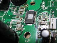
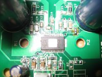
Check the soldering of C14...I can't really tell if it is OK in the second pix.
Check the soldering of the two large input caps...I can't see solder on the input side...Check R5 as well.
160deg C measured by the oven theromstate.Depends on the oven, but I guess not. 160deg C by oven thermostate or measured on board?
May you measure any voltage at the bootstrap pins?
I can measure a few hundret milivolts at the bootstrap pins. Voltage is falling when I leave the multimeter connected.
Checked solder once more and rediti C14. Looks dodgy but seems to be fine. The input voltage appears at the input pins of the tpa.Check the soldering of C14...I can't really tell if it is OK in the second pix.
Check the soldering of the two large input caps...I can't see solder on the input side...Check R5 as well.
Huge thanks to you both for you efforts. Is there any more information I can provide?
The 0V at GVDD should be like 7V, so I would check components there and AVCC that feeds regulator for GVDD
...
Is there any more information I can provide?
Voltage on each side of R4 relative to GND.
Well, if AVCC is up and GVCC is 0V while SDZ is high and no serious current is flowing, the IC is dead for sure if the soldering is right.
If GVCC/GVDD isn't coming up, ohm it out to ground... could be a short hidden under one the pins on the TPA or something.
Got any liquid flux or a flux pen? I'd flux the pins on the TPA and reflow them with a soldering iron.
Got any liquid flux or a flux pen? I'd flux the pins on the TPA and reflow them with a soldering iron.
You don't strictly have to, you can just hook the transformer outputs to the wiener's input terminals and it'll work fine.
Each input has a 30K resistor and zener ESD protector to ground, and a 2.2uF film cap to the INx input of the IC. Resistor and ESD protector shouldn't create any audible effect in this scenario, but the series C will give you a highpass filter at a couple Hz... not that that matters much as the transformer itself probably acts as a higher frequency highpass than it.
@ gmarsh
Thanks! Somehow my reply to you message did not show up??
I recalled that in the TI design, there is a 3 V bias on the differential input. Is this the same with your amp card too? I am not sure whether placing a transformer at the input which carries a DC voltage is OK?
Regards,
Each input is biased to 3V, but there should be negligible DC voltage between the two inputs so hooking up a transformer should be fine. If there is a difference in voltage, the current through the transformer secondary would be the difference (probably single digit mV or less) divided by the sum of the two input resistors at the given gain selection.. it's <1uA. You'll be fine.@ gmarsh
Thanks! Somehow my reply to you message did not show up??
I recalled that in the TI design, there is a 3 V bias on the differential input. Is this the same with your amp card too? I am not sure whether placing a transformer at the input which carries a DC voltage is OK?
Regards,
Last edited:
- Home
- Amplifiers
- Class D
- TPA3116D2 Amp