I'm wondering is it possible that bridge rectifiers are injecting noise to chip's supply pins during normal operation and causing SQ deterioration. I also read somewhere about diodes making noise, so would it be reasonable to remove diodes that protect the board from reverse voltage, in hopes of getting cleaner current. I like living on the edge. 😀
What kind of noise would that be? Thermal and zener noise are an issue in small-signal applications, but not in power supply applications.
That could be one way of doing it. Let us know how it goes with them. I bought 35V 120uF OSCONs, because I'm planning to use 24V power supply and I don't want to be so close to the maximum voltage rating of the capacitor. Might use two VCC/GND pads to add bigger tank caps later.
I'm wondering is it possible that bridge rectifiers are injecting noise to chip's supply pins during normal operation and causing SQ deterioration. I also read somewhere about diodes making noise, so would it be reasonable to remove diodes that protect the board from reverse voltage, in hopes of getting cleaner current. I like living on the edge. 😀
The bridge rectifiers are in the signal-output! The other diodes noises are filtered I guess?
I think one way is to put the board on standby (or maybe mute) when powering on.
I will try this, but first I've to scheck what type of signal to put on the Mute/Stanby connectors of the TPA3116 board.
I'm planning to ask Sure Electronics because there is no documentation on their web site or with the board.
I've worked on three boards now that in stock form provide SD and GND headers: Ybdz ("Weiner"), new Sure tpa3110 and Sure tpa3116. In all three cases, simply shorting those GND and SD headers puts the amp in shutdown mode. I started off using a paperclip, and later installed an actual switch. With the amp in shutdown mode, I get absolutely zero pops/thumps during power on or power off.
I mentioned this earlier in the thread, and someone said it's actually not as simple as straight shorting the TPA chip's SD and GND pins; there need to be some extra components in there. But it appears for the three boards I mentioned, the correct circuit is already in place. But for a board like the YJBlue, you might want to read up a bit before you try to naively invoke shutdown mode.
OpterN, replacing the six power caps by four OSCON SEPF 330 mF/25v really inproved the sound on the Sure TPA3116 board.
I also found this to be true for the new version of the tpa3110 board. In fact I like the Oscon-modded new Sure tpa3110 better than any 3116 board I've played with (stock or modded).
Word of warning
I ordered the TPA3116D2 Feixiang 2.1 amp from Aliexpress and the sub channel has a high whining sound much like a tea kettle, and is causing my woofer to clip even at the slightest excursion. To me that sounds like some busted caps somewhere in the circuit, and potentially a faulty op-amp. I like modding circuits that already work (albeit poorly) from the shipper. This is the 2nd bad amp I got from Aliexpress.com.
Not sure if anyone else faced this issue. Sorry for those waiting to see how my mods turn out, I am stuck waiting for another board!
Which amp or baord did you buy, from what seller?
Last edited:
It's a PCB, no case. I checked it out, the solder job is awful, and the solder being used is pretty bad as well. No visual issues at all, I checked all the pathways from the subwoofer channel. Looks fine high pitching winning and clipping still occurs on the SW channel. Cannot even drive the volume up on the channel. I'll try and replace the caps, but even so, I don't like working off of damaged boards - especially the cheap chinese ones. Since I have now had two feixiang 2.1 TPA3116D2 boards arrive defective, I may switch to another make.
I found the Oscons at Digi-Key for reasonable shipping. I've heard of using four or six on the Sure TPA3116 board. What's the difference? And, yes, I'm a noob.
It's a PCB, no case. I checked it out, the solder job is awful, and the solder being used is pretty bad as well. No visual issues at all, I checked all the pathways from the subwoofer channel. Looks fine high pitching winning and clipping still occurs on the SW channel. Cannot even drive the volume up on the channel. I'll try and replace the caps, but even so, I don't like working off of damaged boards - especially the cheap chinese ones. Since I have now had two feixiang 2.1 TPA3116D2 boards arrive defective, I may switch to another make.
What was wrong with the other ampboard? Did you get to keep it or did you have to send it back?
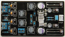
YJ Blue-Black board Modifications
I made the following modifications to the standard YJ Blue-Black board:
Snubber Capacitors: SMD 0603 Multilayer Ceramic 330pF 50v C0G 5%
Snubber Resistors: SMD 0805 10ohm 0.25watt 1%
Bootstrap Capacitors: Multilayer Ceramic 0.22uF 25v X5R 10%
LC Filter Inductors: Coilcraft MSS1210-153MEB 15uH
LC Filter Capacitors: Multilayer Ceramic 0.68uF 50v X7R 10%
Output Filter: Multilayer Ceramic 0.01uF 100v X7R 10%
Input Capacitors: Elna SILMIC II 10uF 35v 20%
Power Supply: Panasonic 25SEPF330M 330uF 25v
I replaced all bootstrap, filter and snubber capacitors with multilayer ceramic capacitors as recommended in the datasheet and Evaluation Board Guide.
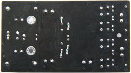
The snubber circuits were added on the bottom of the board using SMD components. By mistake I ordered SMD 0603 size capacitors instead of the slightly bigger SMD 0805 size, so soldering was a challenge.
Given the physical layout of the tracks and ground connections on the YJ Blue-Black board, the 1nF capacitors of the output EMI C-RC Snubber is directly in parallel with then 0.68uF capacitors of the LC filter. The 1nF (0.001uF) capacitor is completely masked by the much larger value 0.68uF capacitor. I have therefore omitted the four 1nF snubber capacitors and simply mounted the 0.68uF filter capacitors in the position of the 1nF capacitors. This leaves more space for upgraded inductors, if required.
The YJ Blue Black Board has a gain setting of 26db with an input impedance of 30kΩ. A -3db bass roll-off at 20Hz, requires a 3.3uF capacitor. I already had the SILMIC II 10uF capacitors on hand and fitted the 10uF and it sounds very good.
The inductors were changed to 15uH, which is a better mach for the 6Ω impedance of my speakers. The inductors also have the same footprint as the original inductors.
Power supply is a laptop SMPS brick delivering 19v at 4A. An additional 4700uF 35v decoupling capacitor is connected directly to the power supply terminals of the YJ board with the power supply wires.
The result is very satisfying and sounds very good, comparable to my NAD system.
I made the following modifications to the standard YJ Blue-Black board:
Snubber Capacitors: SMD 0603 Multilayer Ceramic 330pF 50v C0G 5%
Snubber Resistors: SMD 0805 10ohm 0.25watt 1%
Bootstrap Capacitors: Multilayer Ceramic 0.22uF 25v X5R 10%
LC Filter Inductors: Coilcraft MSS1210-153MEB 15uH
LC Filter Capacitors: Multilayer Ceramic 0.68uF 50v X7R 10%
Output Filter: Multilayer Ceramic 0.01uF 100v X7R 10%
Input Capacitors: Elna SILMIC II 10uF 35v 20%
Power Supply: Panasonic 25SEPF330M 330uF 25v
I replaced all bootstrap, filter and snubber capacitors with multilayer ceramic capacitors as recommended in the datasheet and Evaluation Board Guide.
The snubber circuits were added on the bottom of the board using SMD components. By mistake I ordered SMD 0603 size capacitors instead of the slightly bigger SMD 0805 size, so soldering was a challenge.
Given the physical layout of the tracks and ground connections on the YJ Blue-Black board, the 1nF capacitors of the output EMI C-RC Snubber is directly in parallel with then 0.68uF capacitors of the LC filter. The 1nF (0.001uF) capacitor is completely masked by the much larger value 0.68uF capacitor. I have therefore omitted the four 1nF snubber capacitors and simply mounted the 0.68uF filter capacitors in the position of the 1nF capacitors. This leaves more space for upgraded inductors, if required.
The YJ Blue Black Board has a gain setting of 26db with an input impedance of 30kΩ. A -3db bass roll-off at 20Hz, requires a 3.3uF capacitor. I already had the SILMIC II 10uF capacitors on hand and fitted the 10uF and it sounds very good.
The inductors were changed to 15uH, which is a better mach for the 6Ω impedance of my speakers. The inductors also have the same footprint as the original inductors.
Power supply is a laptop SMPS brick delivering 19v at 4A. An additional 4700uF 35v decoupling capacitor is connected directly to the power supply terminals of the YJ board with the power supply wires.
The result is very satisfying and sounds very good, comparable to my NAD system.
Attachments
It should not be necessary to snubber the bootstrap capacitor if correct type and ratings are observed. The main reason (in my opinion) why people see an improvement here is that it helps overcome the voltage and temperature derating of the bootstrap capacitor.
A part rated for higher voltage and/or higher temperature will show much improved performance and will not need snubbering. 100V X7R should be considered absolute minimum if ceramic capacitors are used.
Further complicating the choice is the fact that they sit on the unfiltered output square wave output meaning the intrinsic piezo effect will also negatively affect performance. This can be helped by choosing low inductance or multi-element ceramics. Both are terminated on the long side making it far more mechanically stable.
However, more modern types like PMLCAPs are far better suited. They also make very good input, LC filter, and DC decoupling capacitors. If you use OSCONs as the large DC decoupling caps then PMLCAPs would be the natural small value partner choice. Due to the very good high frequency stability you'd not need the 1nF capacitor either.
Last edited:
PMLACAP Capacitors
#Saturnus,
I only know about MLCC capacitors.
Can you give a link to a datasheet of these PLMCAP's?
Where can I find more information about these?
#Saturnus,
I only know about MLCC capacitors.
Can you give a link to a datasheet of these PLMCAP's?
Where can I find more information about these?
#Saturnus,
I only know about MLCC capacitors.
Can you give a link to a datasheet of these PLMCAP's?
Where can I find more information about these?
https://www.google.dk/url?sa=t&rct=...=jKobzOHL6h_dartrfpsZVg&bvm=bv.79142246,d.ZWU
Examples of use in a class D amplifier design comparing to MLCC can be found starting page 9.
It's probably the MU series from Rubycon that is the most interesting but I think Panasonic, AVX and Nichicon have similar types.
http://www.rubycon.co.jp/en/catalog/e_pdfs/pmlcap/e_MU.pdf
Last edited:
Input Capacitors: Elna SILMIC II 10uF 35v 20%
I believe this is the first I've seen of anyone (in this thread anyway) using electrolytic caps for DC-blocking input signal caps... any comments on this approach versus film caps?
I believe this is the first I've seen of anyone (in this thread anyway) using electrolytic caps for DC-blocking input signal caps... any comments on this approach versus film caps?
They don't last forever because they're not bipolar. There may also be some audible discrepancy because of it. (Detectable by ear? Not sure)
In general I'd refrain.
Muse ES caps can be used, but I'd use two back to back per channel leg (opposing polarity cap to cap in parrallel). It takes more room, but it balances them.
What was wrong with the other ampboard? Did you get to keep it or did you have to send it back?
Unfortunately the seller asked me to send it back to China nonetheless, they paid for the shipping though! The issue with the other amp board was that the subwoofer channel didn't work at all. Both amps (two different sellers) are giving me sub issues. The channel either falls out, has a high frequency whine (like a tea kettle that is ready). The excursion of the woofer is far too big, and clipping occurs at low volume. I think it's a caps and opamp problem.
Interestingly enough when I take the opamps out there whine is gone, and there is no clipping. This makes sense, there is also almost no volume (logical). I wanted to mention that my received Feixiang 2.1 boards are the brand new Revision 4 boards. All previous boards, including the one shared earlier were Revision 3. I haven't been able to tell what the difference is, except for a broken sub-channel.
Here is a link to images of the board (Feixiang 2.1 Revision 4 - Imgur) , revision 4. I removed the RCA inputs in order to have it properly connect with my pre-amp inputs.
https://www.google.dk/url?sa=t&rct=...=jKobzOHL6h_dartrfpsZVg&bvm=bv.79142246,d.ZWU
Examples of use in a class D amplifier design comparing to MLCC can be found starting page 9.
It's probably the MU series from Rubycon that is the most interesting but I think Panasonic, AVX and Nichicon have similar types.
http://www.rubycon.co.jp/en/catalog/e_pdfs/pmlcap/e_MU.pdf
MU I would have bought if available somewhere🙂 For now I have 2 Dug's completely cog/PML ST, not a single ceramicII on these boards🙂 It is easier to identify what is worse in my linear PSU compared to my SMPS, couldn't hear high frequency problems linear so clear befor, befor only bass was clear. The linear might need shielding from the 3116amps, at this moment my SMPS superior all frequencies to my linear PSU.
They don't last forever because they're not bipolar. There may also be some audible discrepancy because of it. (Detectable by ear? Not sure)
.
You don't need bipolar electrolytic capacitors for the input caps. The input of the TPA3116 chip is biased positive at around 3v and provided your input source does not have a big DC offset, the electrolytic caps will be correctly biased.
You don't need bipolar electrolytic capacitors for the input caps. The input of the TPA3116 chip is biased positive at around 3v and provided your input source does not have a big DC offset, the electrolytic caps will be correctly biased.
Some manufacturers give data for bi-polar operation up to a certain voltage. I didn't know the TPA3116 had a bias on the input there. I wouldn't be surprised if they don't last forever though, as wherever I read about that probably wasn't naive to circuits with a bias on the input.
Personally sound wise I don't like the inconsistency of single electrolytic capacitor sound. Blackgates N were good, but still better in reverse orientation. I use two Muse ES for balance with opposing poles and the results are very good.
Just looking at the Gaincarlo pop avoidance circuit. Good idea, I've used similar circuits with caps charging up to delay the turn on of output relays on some bigger amps, always a quick and easy way of getting a simple delay done.
I have a question though... Why is D1 there? There is an explanation about a negative voltage on the mute pin. Huh? Where is that negative voltage coming from? Do you mean for protection in the event of a voltage spike somewhere? I'd hardly see that as relevant for a simple logic circuit.
I have a question though... Why is D1 there? There is an explanation about a negative voltage on the mute pin. Huh? Where is that negative voltage coming from? Do you mean for protection in the event of a voltage spike somewhere? I'd hardly see that as relevant for a simple logic circuit.
- Home
- Amplifiers
- Class D
- TPA3116D2 Amp