There is no reason why the chips can't perform well with the + & - signal pins floating (connected together via a suitable transformer winding only).
I see one reason why not, it will depend on the grounding of the source and amp. Problems occured with my set-up with my amp ungrounded and fed from an SMPSU. A switching supply is a source of common-mode noise and this will find its way through the trafo's interwinding capacitance with the imposition of a common-mode noise signal at the TPA's input pins. The DS doesn't give the spec for the CM rejection so its not possible to estimate the degree of degradation. At the added complexity of a single cap between the CT and circuit ground this can be mitigated.
I see one reason why not, it will depend on the grounding of the source and amp. Problems occured with my set-up with my amp ungrounded and fed from an SMPSU. A switching supply is a source of common-mode noise and this will find its way through the trafo's interwinding capacitance with the imposition of a common-mode noise signal at the TPA's input pins. The DS doesn't give the spec for the CM rejection so its not possible to estimate the degree of degradation. At the added complexity of a single cap between the CT and circuit ground this can be mitigated.
I see your point, although my preference would be to provide a ground reference to the amplifier board rather than allowing SMPS noise to radiate along signal connections to other components. This would be a better solution and sidestep the need for remedial action at the signal transformers. My TPA3110 amp uses a medical grade SMPS in an external enclosure - the SMPS and chassis are grounded, and I have no issue with noise with the Amethyst input transformers (with electrostatic shield connected or disconnected). My TPA3116 amp has a linear supply and Lundahl input transformers. PSU and signal transformer shields are both tied to ground at the amp board (no issues there either, even when electrostatic shileds weren't grounded).
Good point about the interconnect cable being a radiator, that was something I'd overlooked up until now.
I don't see the reduction of common-mode voltage at the TPA input pins as 'remedial action' though, rather conservative engineering. Since no two grounds are quite alike at HF there are always going to be common-mode currents flowing and it simply makes no sense to allow them to be imposed at sensitive audio inputs.
I don't see the reduction of common-mode voltage at the TPA input pins as 'remedial action' though, rather conservative engineering. Since no two grounds are quite alike at HF there are always going to be common-mode currents flowing and it simply makes no sense to allow them to be imposed at sensitive audio inputs.
I dip in and out of this thread with just enough frequency to remain confused on all the various options. I was browsing the YJ site the other day and stumbled across this unit which I hadn't seen mentioned before.
Yuan Jing Audio - TPA3116 Class-D 2.0 Stereo Amplifier [50W x 2] + USB Audio + Coaxial + Optical + Bluetooth - $115.00
No details on the digital section, unfortunately, and I didn't see anything similar elsewhere on the site that would provide fodder for guessing.
I'm noodling on a multi-way speaker setup using the Nano-Digi, so something like this would be rather convenient. A bit more than I'd like to throw-away on an impulse buy without more concrete info, but cheap enough to be tempting due to the degree to which it would simplify things.
Any thoughts on this guy?
Good point about the interconnect cable being a radiator, that was something I'd overlooked up until now.
I don't see the reduction of common-mode voltage at the TPA input pins as 'remedial action' though, rather conservative engineering. Since no two grounds are quite alike at HF there are always going to be common-mode currents flowing and it simply makes no sense to allow them to be imposed at sensitive audio inputs.
This is a bit at the limits of my knowledge, but I can't see why a transformer with some very small capacitive coupling between the windings would be any worse than a straight DC coupled or AC coupled connection between source and amp. I'd expect the transformer to offer improved isolation.
I just had another look at the Lundahl LL1540 page - they place resistors between pins 5-6/7-8. What is their function and which value would be chosen for the TPA3116?
You support will be appreciated - thx.
You support will be appreciated - thx.
The LL1540 has two secondaries and when these are connected in series the mid point (pins 7 connected to pin 5) is usually grounded, as shown on the datasheet. The two loading resistors are shown between 5-6/7-8 on the basis that 5 & 7 are ground connections.
I haven't grounded 5 & 7 to keep the dual secondaries floating at +3VDC (the bias of the TPA inputs). The TPA chip offers a 30Kohm load for the signal from pins 6 & 8 so no additional resistors need to be added. I did add the 22Kohm+1nF RC network as the load is >25Kohms, in accordance with the datasheet.
All shown here: http://www.diyaudio.com/forums/class-d/237086-tpa3116d2-amp-372.html#post3985800
I don't have time to do the Edcor trafo mod, but if anyone else wants to give the UMM9-PC a try - please do it and let us know how it works. I think this could be the mod that sends this amp into the next level of great sound once the main caps/coil mods have been exhausted. There is still the Avcc de-coupling mod that will require some xacto knife trace surgery to split pin 17 off on its own supply...
There is still the Avcc de-coupling mod that will require some xacto knife trace surgery to split pin 17 off on its own supply...
Well just attempted to lift pin 17 from a Ybdz PCB and managed to break the pin off the chip entirely. It required very little force to do so. My hats off to anybody who has managed to perform this mod - beyond my skills!
I will await the DUG mono PCB that has this mod build in.
I think this could be the mod that sends this amp into the next level of great sound once the main caps/coil mods have been exhausted.
Yes indeed, that transformer mod - together with the rest - turns this 'little' amp into something really special. But don't forget to adjust gain as well - with my tube preamp the transformer alone was good - but only with the gain reduction - unbelievable 😀 .
When it comes to the pin 17 mod - it's beyond my skill as well 🙁 .
Well just attempted to lift pin 17 from a Ybdz PCB and managed to break the pin off the chip entirely. It required very little force to do so. My hats off to anybody who has managed to perform this mod - beyond my skills!
I will await the DUG mono PCB that has this mod build in.
I was going to leave the pin soldered to the pad on the PCB but just cut the solder trace between pad 17 and 18/19 so that it is on its own. Yes, the pins are very fragile as I found out when soldering the chip dead bug style - i.e., "manual wire bonding" to the pins. Thanks for the warning on how fragile it is so I will be sure not to apply any stress to it and just use a really sharp xacto to cut the copper trace between them.
but only with the gain reduction - unbelievable
Dubai,
What gain did you go with? The default 20dB when only one resistor is connected? I will then need a preamp to get back the -6dB loss. What tube pre-amp are you using? I saw a low cost 6N3 tube one on YJ site - is that thing any good?
Yuan Jing Audio - 6N3 Tube Pre-Amplifier Board [ Maratz ] - $35.20
Seems counterproductive to remove gain on amp, just to have to add another bunch of components ahead of it to get the gain back...
I was going to leave the pin soldered to the pad on the PCB but just cut the solder trace between pad 17 and 18/19 so that it is on its own. Yes, the pins are very fragile as I found out when soldering the chip dead bug style - i.e., "manual wire bonding" to the pins. Thanks for the warning on how fragile it is so I will be sure not to apply any stress to it and just use a really sharp xacto to cut the copper trace between them.
Just had a quick attempt at cutting the pin17 trace on my damaged board. To be honest I think lifting the pin more likely to succeed. There is very little room between the pins on the pad that connects to pins 17,18,19, separating them nearly impossible I found.
This is a bit at the limits of my knowledge, but I can't see why a transformer with some very small capacitive coupling between the windings would be any worse than a straight DC coupled or AC coupled connection between source and amp. I'd expect the transformer to offer improved isolation.
That's a rather different conversation - I'm convinced trafos by virtue of providing a higher impedance to common-mode noise are an improvement over a direct connection. Listening reports here support this as offering better SQ. Once having chosen a trafo (as is the current context of discussion) there's no reason I can see not to optimize its configuration.
Yes, in my case 20dB sounds a lot better than 26dB - my preamp is a DIY version (not built by me) of the so-called Grounded Grid preamp offered by Transcendent Sound. I guess the amp's 60Kohm input impedance at 20dB gain simply fits better to the GG.
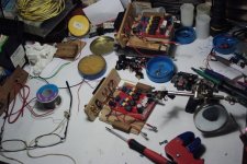
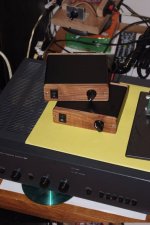
After a month of listening to my YJ 2.0 red amps, I decided it's time to find them a more permanent "home".
Attached is the result: the case is actually aluminium external HDD case, sawn in two 🙂 - got a perfect fit for two amps...
The sound is still great, and now they even look good...
BTW, on the third photo you can see the audio source: Raspberry Pi with Wolfson audio card (up to 24/192), which is definitely the "best buy" in computer audio today... about €100 for a 24/192 bitperfect audio with excellent sound, easily comparable to much, much more expensive devices...
Attachments

Regarding bit-perfect Rasp-pi and the Wolfson, and other S/PDIF-DAC's: I am confused about S/PDIF and DAC's. Why would a DAC have S/PDIF in and out? S/PDIF (stands for Sony Phillips Digital Interface Format) is digital, so where is the "DAC" process happening? Why do we need 192kHz sampling anyway when Nyquist above audible range is 40kHz? Isn't 44.1kHz, 48kHz, or even 96kHz plenty? On top of that, I can't hear above 16kHz, but that's another story... 🙂
Yes, +1 nice looking amps. I like the wood panel on the aluminum box.
Yes, +1 nice looking amps. I like the wood panel on the aluminum box.
Last edited:
- Home
- Amplifiers
- Class D
- TPA3116D2 Amp