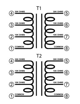
I had a quick look and its unclear if these can be used to give a centre-tapped output (unbal in, bal out). The text at the top suggests that balanced out is possible but it doesn't say if that applies to all combinations - none of the individual line items mention balanced out. Having only impedances (10k/15k/30k) as the spec rather than turns ratios kind of leaves things a bit fuzzy.
Of course they're still usable even with only unbalanced out, but not really ideal.
The circuit diagram shows how the taps are arranged, it would seem that balanced out at 30kohm is just common-30k connections (+ve and -ve amp balanced inputs) and input can be common-30k if you wanted a 1:1 transformer.
Attachments
Yes I looked at that diagram but it doesn't show how many turns are connected to each of the output pins. So it might be that taking the 15k tap (pin6) as the CT (+ and - outputs at 5 and 8, respectively) will work, but just giving the impedances rather than the turns ratios doesn't fill me with confidence.
I had a quick look and its unclear if these can be used to give a centre-tapped output (unbal in, bal out). The text at the top suggests that balanced out is possible but it doesn't say if that applies to all combinations - none of the individual line items mention balanced out. Having only impedances (10k/15k/30k) as the spec rather than turns ratios kind of leaves things a bit fuzzy.
Of course they're still usable even with only unbalanced out, but not really ideal.
You don't need a centre tap on the secondary to connect the transformer to the differential inputs on the TPA (these are already loaded with 30Kohm or so, depending on gain setting, to TPA ground). Also, you wouldn't want to ground a centre tap anyway as this would short the +3VDC TPA input bias to ground.
Looks good to me. I'd connect it using the 30Kohm taps, as this will be equal or close to the input impedance of the amp. Based on the diagram I'd connect + of the unbalanced source to pin 4 and source ground to pin 1. Then connect pin 5 to TPA - input and pin 8 to TPA + input. Go for it!
Any reason why the TPA connection that way round and not 5 to + and 8 to - when pins 1 and 8 are labelled as common?Looks good to me. I'd connect it using the 30Kohm taps, as this will be equal or close to the input impedance of the amp. Based on the diagram I'd connect + of the unbalanced source to pin 4 and source ground to pin 1. Then connect pin 5 to TPA - input and pin 8 to TPA + input. Go for it!
Any reason why the TPA connection that way round and not 5 to + and 8 to - when pins 1 and 8 are labelled as common?
Could well be right - I wondered about that too but went with the orientation in the diagram on balance.
I believe the trade off of the edcors cheaper price is the use of steel vs lundahll nickel core. I'm curious how a side by side comparison would fare...
Could well be right - I wondered about that too but went with the orientation in the diagram on balance.
The diagram is based on the ll1540.
Basically copied from their datasheet here
1540 datasheet
In the 1540, pins 1 and 8 are both labeled as +.
You really just need to be consistent. I would use pin 1 of the edcor for signal low, and pin 8 for output low or you will invert the output.
Randy
These Edcors appear to be a little more hifi - they are mono balanced or unbalanced and come in metal box. $23 ea
https://www.edcorusa.com/m2m15k-15k

https://www.edcorusa.com/m2m15k-15k
Last edited:
You don't need a centre tap on the secondary to connect the transformer to the differential inputs on the TPA (these are already loaded with 30Kohm or so, depending on gain setting, to TPA ground).
Have you tried it? I've tried connecting my DAC to a balanced input with no centre tap on the trafo and haven't had good results at all (a lot of noise). I think I know why - no path for common-mode currents to return to earth. Also without a centre tap there's no way to ensure equal voltage swing on the two input pins, though this is a minor problem.
Sure, you would still use the caps after the trafo to avoid this problem.Also, you wouldn't want to ground a centre tap anyway as this would short the +3VDC TPA input bias to ground.
<edit> I just looked at your link in the subsequent post and see you got the Lundahls working with a similar arrangement. The difference here is those Lundahls come with an electrostatic screen (which you've connected to chassis). Try disconnecting that from your chassis and that'll give you an idea of how well the Edcors will work in this configuration (as they have no screen).
Last edited:
Hi,
I have a pair of Tango input transformer of 600:600R with center tape, can I used it for single end input? Do I just bypass the input cap and connect the secondary winding directly to the INPR and Gnd and INPL and Gnd ?
I have a pair of Tango input transformer of 600:600R with center tape, can I used it for single end input? Do I just bypass the input cap and connect the secondary winding directly to the INPR and Gnd and INPL and Gnd ?
You can't bypass the input caps if you connect the centre tap to GND, you'll still need them.
You can't bypass the input caps if you connect the centre tap to GND, you'll still need them.
Something like that ?

I thought the point of us of the input transformer was to avoid any input caps and have common mode rejection from balanced inputs? Tying to ground and having caps seems to provide only the use of balanced inputs.
@syklab - yes that's the idea.
Input caps can be avoided if the internal reference voltage is brought out of the chip at a low enough impedance. There are no restrictions on how the primary of the trafo is wired, bal or unbal are fine. Common mode rejection comes by virtue of the trafo itself - with no centre tap setting a reference the common-mode rejection job is transferred to the TPA which isn't designed for that.
<edit> Another method might work - remove the two 1uF caps (replace with wires) and put them (in parallel) between the centre tap and GND. This will provide a path for CM currents - how well it works will depend on the inter-winding capacitance of the trafo.
Last edited:
<edit> Another method might work - remove the two 1uF caps (replace with wires) and put them (in parallel) between the centre tap and GND. This will provide a path for CM currents - how well it works will depend on the inter-winding capacitance of the trafo.

Have you tried it? I've tried connecting my DAC to a balanced input with no centre tap on the trafo and haven't had good results at all (a lot of noise). I think I know why - no path for common-mode currents to return to earth. Also without a centre tap there's no way to ensure equal voltage swing on the two input pins, though this is a minor problem.
Sure, you would still use the caps after the trafo to avoid this problem.
<edit> I just looked at your link in the subsequent post and see you got the Lundahls working with a similar arrangement. The difference here is those Lundahls come with an electrostatic screen (which you've connected to chassis). Try disconnecting that from your chassis and that'll give you an idea of how well the Edcors will work in this configuration (as they have no screen).
The transformers work fine without the electrostatic shield grounded. Grounding the shield reduces the capacitive coupling between the primary and secondary (a good thing) but isn't a requirement. Transformers without an electrostatic screen will still be able to do do a good job.
I've used transformers on the outputs of several Vout DACs as well as on the inputs of these amps. I've never found a need to ground centre taps on the DAC output winding or TPA input winding. There is no reason why the chips can't perform well with the + & - signal pins floating (connected together via a suitable transformer winding only). I don't see any advantage to adding a ground connection to the transformer centre tap and then having to introduce caps for AC coupling. That's not to say there isn't a potential advantage (I'm no expert) but I've certainly never failed to get a good result without a ground connection, so haven't seen the need to add one and make things more complicated.
Hi,The transformers work fine without the electrostatic shield grounded. Grounding the shield reduces the capacitive coupling between the primary and secondary (a good thing) but isn't a requirement. Transformers without an electrostatic screen will still be able to do do a good job.
I've used transformers on the outputs of several Vout DACs as well as on the inputs of these amps. I've never found a need to ground centre taps on the DAC output winding or TPA input winding. There is no reason why the chips can't perform well with the + & - signal pins floating (connected together via a suitable transformer winding only). I don't see any advantage to adding a ground connection to the transformer centre tap and then having to introduce caps for AC coupling. That's not to say there isn't a potential advantage (I'm no expert) but I've certainly never failed to get a good result without a ground connection, so haven't seen the need to add one and make things more complicated.
What you are say is I can connect a single ended source to the primary of the transformer, one end of the transformer secondary conects to INPR and the other end to the INNR and leave out the ground?
Thanks
- Home
- Amplifiers
- Class D
- TPA3116D2 Amp