Also, this is what I use: CAIG RSF-R80-2 DeoxIT Rosin Soldering Flux.
I forgot to mention, adding my own solder was one of the tactics I tried for freeing those gain resistor leads. I'm certain I was getting the original solder to flow, though, because I could see the lead moving around freely in the hole (like the analog joystick on a video game controller).
I mentioned this to my dad, and he said someones when excess leads are cut off, the result is a flared end that doesn't pull through. He said you have to push it through enough to cut the flared end off, and only then will the lead come out. I was afraid to work on the top side of the board, because I already ruined one cap being careless with the soldering iron.
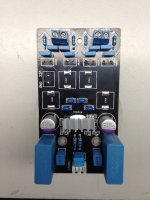
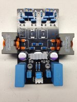
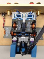
Anyway, below are a couple pics of my "completed" tpa3116 board. I say "completed" only because I'm afraid this board won't tolerate any more of my still-developing soldering skills. 🙂 I think I'm going to have to get another and do some more modding.
Here's a summary of the mods I did:
- Output filter caps (the brownish/organge ones): Panasonic polypropelene 0.68uF 450VDC ECW-FD2W684J4 (DigiKey part number PCF1588CT-ND). This wasn't part of my original plan; I ruined one of the stock output filter caps being sloppy with my soldering iron.
- Output filter inductors: Bourns 22UH 2300HT-220-V-RC (DigiKey M8935-ND). This is basically a bigger, higher-current version of the 2100HT-xxx-V-RC inductors that others reported success with. Bigger is better, right? Well, these are, in my opinion, too big to fit comfortably on the board. I went with 22uH because my speakers (Alpair 7.3) have higher impedance than 4ohms.
- Bootstrap caps: TDK Multilayer Ceramic 0.22uF 250volts X7R FK20X7R2E224K (Digikey 445-2645-ND).
- DC power caps: Elna RFS/Silmic II 330UF 25V 20% RADIAL RFS-25V331MI6#5 (DigiKey 604-1057-ND).
- Gain setting: 5.6 kOhm resistor I had in my parts bin. Other gain resistor completely removed for 20 dB gain. This was done for pedestrian reasons: I'm using this amp in a near-field setup, and it's way too powerful (even with only 12V power supply), so I wanted to lower the gain a bit to give me more play in my volume control. You can see the big blob of messy solder I described above.
- Panasonic 2200uF / 35V cap across the DC power input. Not sure exactly what model this is, had it in my parts collection.
- Volume: Panasonic 50 kOhm log taper EVJ-Y10F03A54 (Digikey P2G1503-ND). A delicate soldering job, but at $1.70, performance to price ratio is off the charts!
I didn't plan out the inductor spacing very well. The big one on top in the picture originally hung out too much and the board wouldn't fit in the case. So I tried to bend the leads a bit, and I wasn't gentle enough, because I ripped the solder pad right off the trace. Fortunately, those traces are wide and in a "non-congested" area, so I just scraped off the resin coating on the trace, and use a short length of wire to connect the inductor lead to the PCB trace. You can't see it in the picture, but that solder job makes my gain resistor job look pretty in comparison. One more reason why this was my "practice" board, maybe version 2 will look more like Rhing's in terms of neatness. 🙂
An externally hosted image should be here but it was not working when we last tested it.
An externally hosted image should be here but it was not working when we last tested it.
I am considering a custom TPA3116 build just to get my head away from my thesis these days which i want to share (open-source style). What are peoples experience with capacitors and coils on this build, which i can take along in the build? Would there be any interest in a PBTL/Monoblock version?
I see a trend towards bigger inductors🙂 Maybe the one silmic is a bit close to donutcenter, don't know if that has an effect.
Anyway, below are a couple pics of my "completed" tpa3116 board. I say "completed" only because I'm afraid this board won't tolerate any more of my still-developing soldering skills. 🙂 I think I'm going to have to get another and do some more modding.
Here's a summary of the mods I did:
I didn't plan out the inductor spacing very well. The big one on top in the picture originally hung out too much and the board wouldn't fit in the case. So I tried to bend the leads a bit, and I wasn't gentle enough, because I ripped the solder pad right off the trace. Fortunately, those traces are wide and in a "non-congested" area, so I just scraped off the resin coating on the trace, and use a short length of wire to connect the inductor lead to the PCB trace. You can't see it in the picture, but that solder job makes my gain resistor job look pretty in comparison. One more reason why this was my "practice" board, maybe version 2 will look more like Rhing's in terms of neatness. 🙂
- Output filter caps (the brownish/organge ones): Panasonic polypropelene 0.68uF 450VDC ECW-FD2W684J4 (DigiKey part number PCF1588CT-ND). This wasn't part of my original plan; I ruined one of the stock output filter caps being sloppy with my soldering iron.
- Output filter inductors: Bourns 22UH 2300HT-220-V-RC (DigiKey M8935-ND). This is basically a bigger, higher-current version of the 2100HT-xxx-V-RC inductors that others reported success with. Bigger is better, right? Well, these are, in my opinion, too big to fit comfortably on the board. I went with 22uH because my speakers (Alpair 7.3) have higher impedance than 4ohms.
- Bootstrap caps: TDK Multilayer Ceramic 0.22uF 250volts X7R FK20X7R2E224K (Digikey 445-2645-ND).
- DC power caps: Elna RFS/Silmic II 330UF 25V 20% RADIAL RFS-25V331MI6#5 (DigiKey 604-1057-ND).
- Gain setting: 5.6 kOhm resistor I had in my parts bin. Other gain resistor completely removed for 20 dB gain. This was done for pedestrian reasons: I'm using this amp in a near-field setup, and it's way too powerful (even with only 12V power supply), so I wanted to lower the gain a bit to give me more play in my volume control. You can see the big blob of messy solder I described above.
- Panasonic 2200uF / 35V cap across the DC power input. Not sure exactly what model this is, had it in my parts collection.
- Volume: Panasonic 50 kOhm log taper EVJ-Y10F03A54 (Digikey P2G1503-ND). A delicate soldering job, but at $1.70, performance to price ratio is off the charts!
Nice work Matt, and thanks for sharing the source and part numbers for the parts. So how does it sound?
I decided to remove the stock inductors and install the Coilcraft SER2915L shielded inductors that wushuliu had posted about. These are chunky inductors, so I moved the terminal block for the power supply to the bottom of the board.
Using the gel flux paste I mentioned earlier, I applied a bit to each solder joint where the stock SMD inductors were soldered to the pads. They came off quite easily and after a cleanup with some Isopropyl Alcohol, the board was ready to accept the inductors. I also tinned the bottom surfaces of the inductor leads where they would be soldered to the pads.

Once I positioned the inductors onto the pads, I used my 40 watt soldering iron to reflow the solder. This took some time as the inductor coils also behaved like a heat sink, but my trusty Metcal iron worked well and I was able to add the two outer inductors first.

To put in the last two inductors, I had to bend the inductor leads a bit to install them at an angle. This arrangement worked out well as it gave me just enough space to fit my soldering iron into the area around the solder pads.


With some careful planning and patience, installing these inductors was pretty straight forward. The amp reminds me of the spaceship Alexei Leonov from the sci-fi movie "2010: Odyssey Two" (sequel to "2001: A Space Odyssey"), or some Minecraft character that my son invented.
Anyway, the amp sounds really nice. I still have to do some extensive listening, but it sounds very clear and transparent. To be honest, I cannot tell if these are better than the Bourns inductors that are similar to Matt's. I tried the Bourns before with another build, and felt they improved the amp's transparency. The Coilcraft inductors are at least equal to the Bourns as far as I can tell. Again, I'll need to do some listening.
Last edited:
Hi Matt,
Have you try MKP or MKT film cap for the Bootstrap caps? Wonder if there is any advantage ?
Have you try MKP or MKT film cap for the Bootstrap caps? Wonder if there is any advantage ?
So how does it sound?
Good. I haven't had time to do any detailed/serious listening. First I just did a check to make sure it worked (that alone made me happy, given some dicey soldering). I also recently changed my speakers, so I've got a lot of moving parts right now. So at this point, I can't give a detailed description of the sonic qualities, except to say that I'm happily enjoying my music right now.
Hi Matt,
Have you try MKP or MKT film cap for the Bootstrap caps? Wonder if there is any advantage ?
I have not... I only have the one tpa3116 board, and the only mods I've done are shown above. The list of components I'd like to experiment with is longer than I'll ever have time for, unfortunately.
PBTL (Mono) Mode
Plan to solder the jumper tomorrow night. Will report the results.
C-:
Plan to solder the jumper tomorrow night. Will report the results.
C-:
PBTL (Mono) Mode
(Please comment if the following mod will work and suggest any corrections.)
For the Black YJ board the following modifications are required:
- solder a three way jumper on the bottom of the board, shorting C10 and connected to the output side of C33
- jumper the ROUT terminals
- jumper the LOUT terminals
For the input use RIN and connect the speaker between ROUT and LOUT.
Hi Matt,
Have you try MKP or MKT film cap for the Bootstrap caps? Wonder if there is any advantage ?
All unmodded blueboards have MKT bootstrap caps I think
6 channels for NaO Note II RS
Hi all,
After a successful tpa3116 build I am looking for a 6 channel amp solution.
Lookin to build the NaO Note II RS speaker, it requires 8 channels in total. I was thinking of using a 6 channel 3116 PCB for high, mid and lower mid range, and two bridged LM4780 to power the bass.
The NaO Note II RS uses the mini DSP system for the crossover, the model required varies on amp choice. This leads me to my question....
Can the tpa3116 & lm4780 be driven to full output with a max input of 0.9V?
If they can, would allow using the cheaper 2x4 minidsp, instead of the 4x10.
Many thanks
Ian
Can the tpa3116 & lm4780 be driven to full output with a max input of 0.9V?
If they can, would allow using the cheaper 2x4 minidsp, instead of the 4x10.
Many thanks
Ian
MiniDSP can output 2v (revB).
TPA3116 has 4 selectable gains, the highest of which (36dB) is more than adequate to swing the output to clipping from 0.9V input. An LM4780 can have virtually any gain you like above 26dB (just choose the feedback network resistor values to suit) so also can be driven from 0.9V.
MiniDSP can output 2v (revB).
Actually revB miniDSP can take 2V rms at input as opposed to 0.9V rms for revA, but both only output 0.9V rms 😉
Actually revB miniDSP can take 2V rms at input as opposed to 0.9V rms for revA, but both only output 0.9V rms 😉
Thanks for correcting me, I do recall it was input now.
I have been working under the assumption that it was 2v output, no wonder I wasn't getting the gain I expected!! Maybe I will move to the miniSHARC and use I2S connected DACs with 2v output.
Sorry, off topic!
I have no clue, but trying🙂
So how do you calculate exactly? 20dB gain increases 0.9V to 9V? In BTL +9V and -9V so 18V swing to speaker from 0.9V input? In BTL load seen is halved so for 4 ohm load you get 18V*18V/2*2= 81Watt ? Would that imply 0.9V input with 20dB gain already exceeds max output here?
So how do you calculate exactly? 20dB gain increases 0.9V to 9V? In BTL +9V and -9V so 18V swing to speaker from 0.9V input? In BTL load seen is halved so for 4 ohm load you get 18V*18V/2*2= 81Watt ? Would that imply 0.9V input with 20dB gain already exceeds max output here?
PBTL (Mono) Mode Mod
I can report that it works well.
Tell me if I should update the wiki please.
Plan to solder the jumper tomorrow night. Will report the results.
C-:
I can report that it works well.
Tell me if I should update the wiki please.
Hello Guys,
I'm new and i've chosen to buy a TPA3166d2 board since it seams a bang for the buck hero, but i have two Questions.
1. Which one has the best layout and components? how about this one: TPA3116 ClassD Amplifier Board 50W+ 50W Filter Capacitor 10000UF D Class | eBay
first one i found.
2. I don't want to read through the 321 sites of this thread so could someone please explain the most essential tweaks?
I only have build some Loudspeakers and now i really want to get into building amps and other electronics but i don't have much knowlege yet so please be gentle 🙂
I can report that it works well.
Tell me if I should update the wiki please.
yes.
with pics please.
Poeple like this one 2 Channels TPA3116 Amplifier Assembled Board 50W 50W | eBay
Could you somehow explain why this board is better? I'm not very good at this yet and i'd like to soak up as many knowledge as possible.
- Home
- Amplifiers
- Class D
- TPA3116D2 Amp