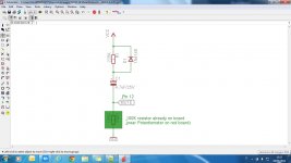
I've attached the schematic of a antibump circuit that I successfully tested on red board.
I'm pretty sure that it works fine for blue board too.
It takes only three components:
1 Resistor 220K
1 diode 1n4148
1 capacitor 4.7uF/25V
Only two connections are needed between circuit and board:
A wire to positive of power supply (+Vcc)
A wire to a 100K smd resistor (already on board), that is connected to pin 12 (mute) of the TPA3116.
Attachments
So still no observations regarding changing gain? No one's compared 36 vs. the rest? I think folks are missing out on improved presentation by not trying 36db although yes you may need to increase input capacitance a little to compensate (I use 2.2uf).
Too bad those ebay tube preamps are such high gain or I'd try them. Will have to go with a unity gain buffer instead at some point.
26db sounds flat and bland on all the TPAs (3100, 3116, 3110) I've ever had compared to 32 and 36 gain setting.
Would it be possible to lower the gain on the tube preamp?
I've attached the schematic of a antibump circuit that I successfully tested on red board.
I'm pretty sure that it works fine for blue board too.
It takes only three components:
1 Resistor 220K
1 diode 1n4148
1 capacitor 4.7uF/25V
Only two connections are needed between circuit and board:
A wire to positive of power supply (+Vcc)
A wire to a 100K smd resistor (already on board), that is connected to pin 12 (mute) of the TPA3116.
On power down the mute pin will get pushed to -Vcc.
Hope it survives.
I would have put the diode across the mute input to GND...protecting it from -Vcc. (and used a 1A diode)
Even then: Max input to MUTE is -0.3V (data sheet) and only needs to go to 2V to activate.
🙂
Last edited:
On power down the mute pin will get pushed to -Vcc.
Hope it survives.
I would have put the diode across the mute input to GND...protecting it from -Vcc. (and used a 1A diode)
Even then: Max input to MUTE is -0.3V (data sheet)
🙂
There is already a protection diode internally in TPA3116.
I've already measured voltage on pin 12 and during discharge voltage is only -0,5V..-0.6V.
You can measure that diode with a multimeter.
Here is a link to an italian forum where yesterday I've posted a schematic with that optional diode:
TPA 3116 - Pagina 53
..and a few hours ago I wrote in the same forum that the diode is not needed, because there is already one inside the chip (sorry for italian):
TPA 3116 - Pagina 59
My TPA3116 is ok. I've not burned it, and I've done a lot of poweroff cicle.
In any case it is possible to add another diode between pin 12 and gnd (anode to Gnd).
Dug you are right!
Thank you to have pointed out that maximum negative voltage on pin 12 is only -0.3V.
There is already a protection diode internally in TPA3116, but obviously is a silicon diode that have a 0.6V forward voltage.
I will add a protective schottky diode (or germanium diode) that have a lower forward voltage.
I've have attached another antibump schematic with a mosfet.
In this case there will be not problem at all on mute pin, but I've not tested yet this circuit.
What do you think?
Thank you
Attachments

There is already a protection diode internally in TPA3116.
I've already measured voltage on pin 12 and during discharge voltage is only -0,5V..-0.6V.
You can measure that diode with a multimeter.
...
I am unable to find (in the data sheet) any reference to protection diodes on the MUTE input.
It may be just a coincidence that it measures as a diode and will clamp at " -0,5V..-0.6V. ".
I don't dispute your results.
On other devices when there is a protection diode clamp on an input there is usually a maximum current rating that applies to the clamping diode.
Did not find that either.
Just saying that I would limit current if reverse potential is applied to MUTE or other inputs.
Good luck.
🙂
Hello! Two quick questions if it's okay 🙂
1. After an upgrade of storage capacitors to 35V type, is there any reason that the blue board will not work at 26V?
2. Is 2000uF storage sufficient for full operation? Expected output is 120WRMS with impedances & Vin.
Thanks in advance,
1. After an upgrade of storage capacitors to 35V type, is there any reason that the blue board will not work at 26V?
2. Is 2000uF storage sufficient for full operation? Expected output is 120WRMS with impedances & Vin.
Thanks in advance,
While waiting for my new inductors and Jupiter input caps to arrive, I set up my TPA3116 for switchable gain (20dB, 26dB & 32db) and for testing different values of input coupling caps (from .5uF to 10uF).
My first impression is that I prefer the lowest gain setting (20dB) with somewhere between 1.5uF - 3uF input coupling caps, but will spend some more time listening this weekend and revisit it all after the inductors arrive.
It just goes to show you how system dependent different speakers, equipment and component parts can be.
I’m sharing Rhing’s preference for smaller decoupling caps close to the chip and am now experimenting with some arrays of multiple caps off the power supply like abraxalito suggests. I’m still using the second adjustable linear regulated supply that I built last month (set at 23V) and enjoying how it's all sounding.
.
KJA,
Please keep us posted.
Regards,
what is the most cost efieiceint way to add power to 2 of the 3116 boards in PBTL mode
TPA3116 Class D Power Amplifier Board Support Stereo 50WX2 or Mono PBTL 100W | eBay I still want the full value of the amp's sound to come though,will one brick power 2 boards.help me I am not very good with electricity
TPA3116 Class D Power Amplifier Board Support Stereo 50WX2 or Mono PBTL 100W | eBay I still want the full value of the amp's sound to come though,will one brick power 2 boards.help me I am not very good with electricity
what is the most cost efieiceint way to add power to 2 of the 3116 boards in PBTL mode
TPA3116 Class D Power Amplifier Board Support Stereo 50WX2 or Mono PBTL 100W | eBay I still want the full value of the amp's sound to come though,will one brick power 2 boards.help me I am not very good with electricity
What is the impedance of your speakers?
...
1. After an upgrade of storage capacitors to 35V type, is there any reason that the blue board will not work at 26V?
...
Did it work at 26V before you modified it?
...
2. Is 2000uF storage sufficient for full operation? Expected output is 120WRMS with impedances & Vin.
...
120WRMS: PBTL and 2 ohm speakers...data sheet says it should.
Can your power supplies supply the power required for your expected output?
At 120WRMS output you will need a power supply good for at least 140W.
Is the heat sink able to dissipate 20W?
Hi DUG,
Yes, amplifier works fine at 22V, very happy with it 🙂
The 120WRMS is total, Ch1 operating at 4R (80W), Ch2 operating at 8R (40W). Heatsink is currently original part. Will perhaps need to keep and eye on thermals and replace if required (have the feeling it's undersized?)
Power supply is Li-Ion pack! (10A regulated 18650 array)
What is the impedance of your speakers?
they are 4 ohm ADS L710's oh and the brick is 12v-24v variable @6A and do I need to cut the plug or is there a Y connecter I can use.Thanks
Some tips, concerning SDZ & MUTE function, from TI's forum.
TPA3130D2 SDZ & MUTE - Audio Amplifiers Forum - Audio Amplifiers - TI E2E Community
TPA3130D2 SDZ & MUTE - Audio Amplifiers Forum - Audio Amplifiers - TI E2E Community
Help calculating output filter component values.
Forgive me if this information is contained elsewhere in this thread.
I understand component values for the output filter are dependent on speaker impedance.
How do I calculate the ideal capacitor value for the output filter to give the flattest response for 6 Ohm speakers using a 10uH inductor.
My speakers are nominal 6 ohm impedance (Mark Audio Alpair 7 full range) and I have already have the Bourns 10uH inductors recommended by others.
I read earlier in the thread that 15uH / 1uF is ideal for a 6 ohm load but would rather use the 10uH Bourns inductors I have and change the capacitor value. (BTW I’m modifying the YJ Blue/Black board)
Any help much appreciated. 🙂
they are 4 ohm ADS L710's oh and the brick is 12v-24v variable @6A and do I need to cut the plug or is there a Y connecter I can use.Thanks
So your supply is 144W. (24V * 6A)
You should not expect any more than 115-120Wrms TOTAL audio power from any class D amps you hook up to it.
Forgive me if this information is contained elsewhere in this thread.
I understand component values for the output filter are dependent on speaker impedance.
How do I calculate the ideal capacitor value for the output filter to give the flattest response for 6 Ohm speakers using a 10uH inductor.
My speakers are nominal 6 ohm impedance (Mark Audio Alpair 7 full range) and I have already have the Bourns 10uH inductors recommended by others.
I read earlier in the thread that 15uH / 1uF is ideal for a 6 ohm load but would rather use the 10uH Bourns inductors I have and change the capacitor value. (BTW I’m modifying the YJ Blue/Black board)
Any help much appreciated. 🙂
You use a Zobelfilter to make 15khz and/or 20khz 6 ohm too?
Forgive me if this information is contained elsewhere in this thread.
I understand component values for the output filter are dependent on speaker impedance.
How do I calculate the ideal capacitor value for the output filter to give the flattest response for 6 Ohm speakers using a 10uH inductor.
You can use this RLC Low-Pass Filter Design Tool calculator . Works like a charm
- Home
- Amplifiers
- Class D
- TPA3116D2 Amp