Thanks a lot, distortion profil conform really well what was expected.Here are some first measurements of this little beast.
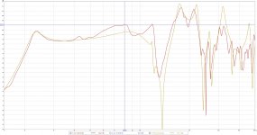
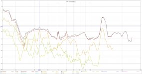
I have overlaid the raw response with the as-used response with EQ and Xover using my MiniDSP 2X4HD. All the measurements are taken indoors with an Umik microphone and REW. Microphone 5 cm from the port on one side of the box (there are two ports. One on each side). No smoothing. The distortion graph has some small peaks where it does indeed get close to a single percent THD, but overall the THD is centered around the 0,5 percent level for most of the passband.
When scanning though the passband in the distortion graph it is very clear that the distortion is highest in the lower part of the passband where there is no acoustic positive feedback. From 50 Hz and upwards the positive feedback makes the driver behave like it had a lot more Bl and moving mass - a much more powerful driver.
I measured from 10 Hz to 500 Hz in order to get a decent amount of the out of passband ripple and distortion. The ripple peaks 6,3 dB (not quite 15 dB) above the peak of the passband. I guess there are other ways of weighting this kind of comparison but I just took the most obvious example first. I am sure someone will tell me a better way more to your liking if anyone wants it.
H3 between 50-70hz = distortion acting in 150-210hz just right in the spike.
H3 dip around 46hz =right in you dip at 138hz
H2 spike at 40 hz = right in the 80hz response spike
H5 spike at 40 hz = right in the 200 hz response spike
H3 at 33hz spike => this one, and some others, weren't expected ^^
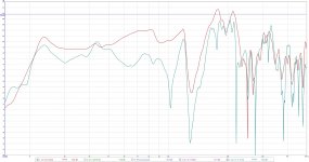
Here is the Hornresp simulation compared to actual measurement.
Close enough.
The same driver in a 23 Hz tuned BR will most certainly have at least 10 times the measured THD over large parts of its passband, so I am very happy with the performance of this design.
A measured THD centered around 0,3 % in the midbass where it is most important due to the distortion products being in the very sensitive midrange is pretty impressive considering that this is a home theater oriented sub.
Close enough.
distortion profil conform really well what was expected
The same driver in a 23 Hz tuned BR will most certainly have at least 10 times the measured THD over large parts of its passband, so I am very happy with the performance of this design.
A measured THD centered around 0,3 % in the midbass where it is most important due to the distortion products being in the very sensitive midrange is pretty impressive considering that this is a home theater oriented sub.
Attachments
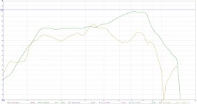
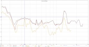
Here is the reason why I always want a midbass peak.
The room gain profile always tend to tilt the response curve the wrong way and make it sound bottom heavy and "slow".
Red curve is 5 cm from the mouth. The green curve is in my living room sofa where I usually sit when I watch movies and listen to music.
No smoothing, Xover or EQ in any of the measurements.
Now imagine a "flat" response in the same acoustic environment.....
Attachments
Of course, with high order low pass (48db/oct is not something everyone accept), and right EQ, i can only agree, this is a interesting design compared to reflex, and a alternative to tapped horn problably easier to build.A measured THD centered around 0,3 % in the midbass where it is most important due to the distortion products being in the very sensitive midrange is pretty impressive considering that this is a home theater oriented sub.
But if i can add again a bit of itching powder, depending on the information you provide, you've claimed >140db power with one design, without figuring THD, and now, 0,3 % THD without figuring the exact level. This is confusing

This is the measurement from the car spl dragrace comp the owner of the HROAR10 attended. I was not there and I have not seen any FFT of the measurement they made. Everyone who heard this design at +140 dB demos he regularly made while waiting for his dB dragrace comp, commented on how clean and punchy it sounded. Most people guessed at two 12s or two 15 inch drivers with copious amounts of power. Nobody believed him until they saw it with their own eyes that it was only a single 10 inch driver and 3500 watts of power.
I don´t know if Thermlab dB Drag Racing Term-LAB SPL Meter has FFT capabilities or if it is interesting considering the violent rattling and buzzing of the interior of the car at those sound pressure levels. I would guess the distortion and noise makes up 20 percent of the total spl, which in that case would make it much better then most bass reflex boxes.
and now, 0,3 % THD without figuring the exact level
143.88 dB is based on a standardized spl comp setup. A thermlab mic on the right side of the windshield.

Here it has 0,308 percent THD at 104 dB 5 cm from the mouth. I don´t know the exact power at that exact frequency, but it is a quite exact defined level.
You can see here in post #28 the level of distortion reduction that can be expected with a simple but well implemented bandpass, a Brian's awesome reworking report.
H3 between 50-70hz = distortion acting in 150-210hz just right in the spike.
H3 dip around 46hz =right in you dip at 138hz
H2 spike at 40 hz = right in the 80hz response spike
H5 spike at 40 hz = right in the 200 hz response spike
Thanks for doing the math showing the correlation between the out of band peaks and the distortion products withing the passband. Very interesting!
Since the over all level of distortion is quite low, and it sinks with increasing frequency, it does not worry me that much for normal indoor listening levels.
I hope the sun will visit us again here on the 58th parallel north before the end of November. I want to do some outdoor measurements at higher power levels.
Here are some first measurements of this little beast.
FWIW, I found that plotting distortion normalized to the fundamental is more revealing of a system's distortion characteristics. Can you the THD curves for the build with the distortion normalized to the fundamental please ?
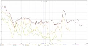
Like this?
That's it, thanks.
Also, usually I don't bother plotting anything above the 3rd harmonic, unless the system has some audible issue that I'm trying to identify and resolve. Makes for a less "busy" graph
H3 at 33hz spike => this one, and some others, weren't expected ^^
Check the 6th Harmonic 🙂
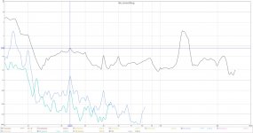
Interesting results! Good agreement between simulation and measurement.[
View attachment 794227
Here it has 0,308 percent THD at 104 dB 5 cm from the mouth. I don´t know the exact power at that exact frequency, but it is a quite exact defined level.
Could you measure at 1 m distance and 90, 100 and 110 dB? I think that would make it easier to compare to other speakers (more common to measure at that distance when looking at distortion).
On another note: I am toying with the idea of building a very light tapped horn (glass fiber/epoxy and foam sandwich) that would require a push-pull configuration for force cancellation. How would you fold that? Usage would be as a party subwoofer. Maybe something like this:

/Anton
Or maybe better like this (one output instead of split into two):Interesting results! Good agreement between simulation and measurement.
Could you measure at 1 m distance and 90, 100 and 110 dB? I think that would make it easier to compare to other speakers (more common to measure at that distance when looking at distortion).
On another note: I am toying with the idea of building a very light tapped horn (glass fiber/epoxy and foam sandwich) that would require a push-pull configuration for force cancellation. How would you fold that? Usage would be as a party subwoofer. Maybe something like this:
View attachment 794254
/Anton

/Anton
Looking at the processed response I have a hard time imagening the above passband distortion components would be noticable once the design is properly integrated with a top system.
I would even go a bit further and suggest that a higher xo should be possible without noticable issues, but this is mere speculation given that the circumstances around the processed response measurement is not standardized with regards to input power, distance and acoustic environment.
I would even go a bit further and suggest that a higher xo should be possible without noticable issues, but this is mere speculation given that the circumstances around the processed response measurement is not standardized with regards to input power, distance and acoustic environment.
"diyAudio - projects by fanatics, for fanatics" 😀Looking at the processed response I have a hard time imagening the above passband distortion components would be noticable once the design is properly integrated with a top system.
I would even go a bit further and suggest that a higher xo should be possible without noticable issues, but this is mere speculation given that the circumstances around the processed response measurement is not standardized with regards to input power, distance and acoustic environment.
- Home
- Loudspeakers
- Subwoofers
- TP12LL34 Duality and positive feedback