What codyt said. Start with higher values for the series resistor, say 2-3R and work down from that. If you have a variac and are feeling adventurous, you could start with a lower value and slowly bring up the voltage. Put your probes to measure the current and see what you are getting. Either way, it should be doable.
We wouldn't be able to use this topology on the Sony VFETs coz they need much more volts between the gate and source.
We wouldn't be able to use this topology on the Sony VFETs coz they need much more volts between the gate and source.
Last edited:

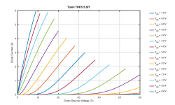
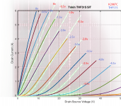
I found some measurements Woofertester made of thf51, and I superimposed it with a measurement that wangweiliangb shared in his original post on the K2087. I was able to warp things up so that the vertical and horizontal div's are the same.
Granted, these are two different testing environments done on two different devices, but its still an interesting look. To me, it seems like the curves are pretty similar and thf51 just needs to pull Vgs just another volt or so to bring it more inline with K2087.
Granted, these are two different testing environments done on two different devices, but its still an interesting look. To me, it seems like the curves are pretty similar and thf51 just needs to pull Vgs just another volt or so to bring it more inline with K2087.
Attachments


I found some measurements Woofertester made of thf51, and I superimposed it with a measurement that wangweiliangb shared in his original post on the K2087. I was able to warp things up so that the vertical and horizontal div's are the same.
Granted, these are two different testing environments done on two different devices, but its still an interesting look. To me, it seems like the curves are pretty similar and thf51 just needs to pull Vgs just another volt or so to bring it more inline with K2087.
In your estimation, would the 2SK182ES TOKIN also work as well here?
I think I'd be willing to try any of the Tokin devices in this design. I can't say to what extent you'd have to vary Vgs, but as long as some precautions are taken (temporary inline fuse, maybe a variac, etc) I wouldn't hesitate to give them a whirl.
On a side note, it would be awesome to find someone who has a nice collection of Tokins and a curver tracer – I'd love to see a legit overlay of the different device types swept across the same parameters. Who knows, maybe that's already out there...
On a side note, it would be awesome to find someone who has a nice collection of Tokins and a curver tracer – I'd love to see a legit overlay of the different device types swept across the same parameters. Who knows, maybe that's already out there...
The Tokins do have a lot of variation from sample to sample. So unless your Tokins are curve traced, you can't know what your Tokins' need for Vgs at a particular Iq. But curve tracing could be used to search out some operating parameters.
One way to figure out a particular sample's Vgs is to connect an adjustable bias supply (negative voltage) along with the choke at the source. Adjust the bias supply until the desired Iq is reached. The bias supply voltage at that point is the voltage that is needed to be dropped if a source resistor replaces the bias supply voltage. A possible issue is if the sample has too low of a Vgs, the choke may already set Iq below what is desired. Then a positive voltage bias supply would be needed to drop Vgs to get the desired Iq. But probably most samples will not have this issue.
I have built a 2SK180 choke loaded (Hammond 193V) follower with a bias supply. I ended up with 2.5A and about 38V power supply (35.5Vds). That was good for close to 25W at 8 Ohms. I think that would be a good starting for trying out the THF-51S or 2SK182ES.
on the self bias version, is it accurate to say that R1 (6k-10k) is determining the input impedance of the amp?
I’ve experimented with 20K and have had no issues with bias stability. Can you remind me the max resistance you’ve used in this position? I have a buffer and autoformer combo that I’m trying to mate with my TDV and looking for as much input impedance as I can get, without stability issues of course.
If you are asking when I felt safe listening to the amp without meters, the value is 10k  … but that was only one device. The other was stable at higher values. Your set might be better.
I’d suggest monitoring for 3-4 hours and see the drift. Mostly you’ll know in the first 20 mins if the bias is going to hold.
On some gate bias configs, I also saw a kind of sudden runaway… where it would climb slowly until 1.7A and then runaway rapidly afeter that. But that was with gate bias. Shouldn’t happen with source bias.
If 20k isn’t an issue, go up to 47k and see if it sticks.
… but that was only one device. The other was stable at higher values. Your set might be better.I’d suggest monitoring for 3-4 hours and see the drift. Mostly you’ll know in the first 20 mins if the bias is going to hold.
On some gate bias configs, I also saw a kind of sudden runaway… where it would climb slowly until 1.7A and then runaway rapidly afeter that. But that was with gate bias. Shouldn’t happen with source bias.
If 20k isn’t an issue, go up to 47k and see if it sticks.

My thf51 choke loaded follower with a bias supply, after 60 mins, has a channel with these measures:
Vds = 26.74V Vg = -3.28V Id = 2.42A
The other channel is very similar. R1 is 18K.
When I connected the amp to the computer for measurements I noticed a small oscillation in the voltage on the drain. It disappeared changing R2 from 22R to 100R.
Vds = 26.74V Vg = -3.28V Id = 2.42A
The other channel is very similar. R1 is 18K.
When I connected the amp to the computer for measurements I noticed a small oscillation in the voltage on the drain. It disappeared changing R2 from 22R to 100R.
While I wait for parts to arrive, I was wondering if a 70V speaker distribution transformer would work in place of the output cap and maybe even the choke? I have several I could try including a UTC with taps for 25W and 50W. I would arrange similar to a parafeed transformer used in tube amps (primary connected to ground with a cap for DC voltage).
You could try the parafeed config but not in place of the choke because of DC current, as ZM states. So, you’d need this trafo plus a choke or another load.
http://tubelab.com/articles/ideas/single-ended-output-stages/
http://tubelab.com/articles/ideas/single-ended-output-stages/
- Home
- Amplifiers
- Pass Labs
- Total Domination VFET (TDV) Amp (using 2SK2087C)