Yeah, should work just fine. It looks like the the 193 series but without the end bells. And in fact it has a bit more inductance at 60mH compared to 50 mH with the 193T. Looks like a great choice.
Mike’s MoFo article is a good guide on choke choices. Really, you could go bigger with this device assuming there is adequate heatsinking. The amount of extra resistance needed beyond what the choke provides might have to change with different chokes. But I have not tested that and I don’t know how the gate will behave at those operating points with higher currents.
Mike’s MoFo article is a good guide on choke choices. Really, you could go bigger with this device assuming there is adequate heatsinking. The amount of extra resistance needed beyond what the choke provides might have to change with different chokes. But I have not tested that and I don’t know how the gate will behave at those operating points with higher currents.

The 159ZC is perfect, a friend of mine is using it in his MoFo and it’s been also use by many in the Big MoFo which has a bias of 2.5A, choke wasn’t overheating but I assume the 60mH went down a little.
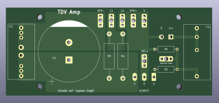
I really like ra7's schematic from post #26. Though this circuit really begs for a quick point to point build, I had some time to fill yesterday and made a quick board to fit the UMS pattern. I just ordered 5 boards and will be able to build toward the end of the month. Feel free to use them anytime, just know I haven't verified yet.
Attachments
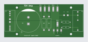
For those on the fence about ordering boards, you can get five of these shipped from JLCPCB to the US for under $10.
Good work.
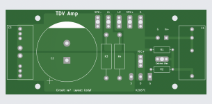
With a change or two you can make the board universal. All it needs is an option to add a bias voltage at the gate.
With a change or two you can make the board universal. All it needs is an option to add a bias voltage at the gate.
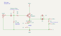
Couldn’t R1 next to C1 serve that purpose? R1 likely won’t be used if you are connecting the gate to a bias voltage.
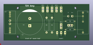
Ok, I think this would do it. User would leave R1 unstuffed, use the external bias entry, and jump R3 and R4. Theoretically I suppose one could just use the right through hole for R1 as entry point, but I do like this one.Good work.
With a change or two you can make the board universal. All it needs is an option to add a bias voltage at the gate.
Attachments
Fantastic developments here Fellas! Thanks for sharing the Gerbers Cody.

This single output device layout begs for a CPU cooler/Noctua a’la MoFo for cooling.
This single output device layout begs for a CPU cooler/Noctua a’la MoFo for cooling.
You're welcome.Thanks again for that suggestion, Ben. Here's a new set of gerbers
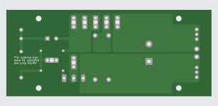
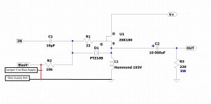
I am wondering whether it makes a difference whether that bias voltage is applied after R1 as you have done or before R1 as I have seen on schematics. It would be an easy change - locate the bias voltage connection where you show R1 and move R1 to be in series with the bias voltage connection. Jumper the bias voltage connection if it is not used.
The reason I thought a universal follower board would be good is because it seems to me that the majority of diyAudio members will only build an amplifier if boards are available. With a universal board, a builder could choose from a variety of Tokins and N channel VFETS, and various loads. It would be a Follower L'Amp. 🙂
Very interesting design! Between this and the Scryer, I think I’ll be set for SIT amps for a while. 😆
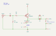
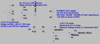
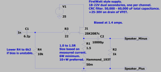
Thanks Ben, those are good questions/suggestions. I'm attaching the schematic that these last boards are based on. Looking at ra7's earlier schematics, it seems R1 is not connected when an external bias is used (referencing post #1 schematic as external bias example). The later versions which focus on 'self-biasing' use the R1 (6k-10k) connection. In my mind, I was thinking a builder could either build the self-biasing version (stuff all parts, no external bias connection), or build an external bias version (omit R1, use regulated voltage source connected via 'external bias' on board).
All that said, I could be missing something entirely 🙂
edit attaching the two options I was trying to accommodate
All that said, I could be missing something entirely 🙂
edit attaching the two options I was trying to accommodate
Attachments
Last edited:
Ok, I see what you have done.
What I am suggesting then is a third option, which is typically done for applying bias voltage. It would make the board more universal. It might be attractive to some builders, to encourage them to build a follower amp, whether ra7's, or one of other versions out there.
Me, I'm comfortable with my veroboards and stripboards. 🙂
Attachments
- Home
- Amplifiers
- Pass Labs
- Total Domination VFET (TDV) Amp (using 2SK2087C)