If I am correct and there are slots lower down shown in the rendered image, (if not one could considder adding them in the box's base) I would suggest that a way out for the hot air in the top of the box be found/added. Wood is quite a good insulator after all. This would then in effect act as a heat chimney similar to the early Sony VFET amps.

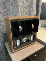
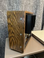
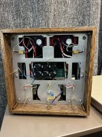
Oak wood case has been finished and the chassis mounted within. The chassis assembly slides into the box and is fixed by the 3 screws on either side. Still need to wire up the I/O shield and get the front grill and backplate fabricated.
Would have finished up the wiring tonight but a sudden nasty bout of food poisoning mid-soldering derailed those plans… Feeling a bit better, but impatient to get this thing done!
Would have finished up the wiring tonight but a sudden nasty bout of food poisoning mid-soldering derailed those plans… Feeling a bit better, but impatient to get this thing done!
Attachments
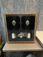
Oak wood looks superb! Difficult to bring out the grain like that, IME  Really neat build.
Those heatsinks are not going to be enough I suspect. Did you have a plan in mind? Might want to add some active cooling. I am trying things out with the 193V and more bias and for that I added a fan. Works like a charm. Running it off the amp supply and a 12V zener follower. Now my sinks are cooler than even at lower bias. I’ll post some pics.
Really neat build.Those heatsinks are not going to be enough I suspect. Did you have a plan in mind? Might want to add some active cooling. I am trying things out with the 193V and more bias and for that I added a fan. Works like a charm. Running it off the amp supply and a 12V zener follower. Now my sinks are cooler than even at lower bias. I’ll post some pics.
I’m interested to see pics of your fan setup. I’m prepared to add some fans and additional sinks if the current setup doesn’t pan out. I think I will be right on the edge of acceptable, but we shall see.Oak wood looks superb! Difficult to bring out the grain like that, IME
Those heatsinks are not going to be enough I suspect. Did you have a plan in mind? Might want to add some active cooling. I am trying things out with the 193V and more bias and for that I added a fan. Works like a charm. Running it off the amp supply and a 12V zener follower. Now my sinks are cooler than even at lower bias. I’ll post some pics.
Here's a pic. The heatsinks are 12" x 3". The devices are right down the middle on the sinks. The fan is mounted midway across and to the top, away from the devices. There are two holes on the top just south of the devices, with the idea that air is drawn into the chassis from the holes, moves near the device and is exhausted from the fan. There is no other ventilation holes and earlier, at lower bias of about 1.7A where the heatsinks got hot, I simply operated it with an open top.
Using the big 193V inductor, it biases at 2.4A on one channel and 2.0A on the other. This is because my 2SK2087s are not matched, as I'm sure is the case with nearly everyone and any SIT. I connected 0.23R across the one with more bias to bring it down to 2.0A, whereas the choke alone provides the bias on the other channel. I am doing more listening and figuring it out at this time, but the bottomline is that you are not guaranteed to get to 2.5 or 3.0A with every device using the 193V under this topology. A choke with a lower DCR is needed for higher bias. You might luck out and end up with two devices that both bias up to 2.5A or some other value and then you'll be golden, but it is not guaranteed. Also, be prepared to use resistors along with the chokes at least on one channel to match the other.
So, that's about 2A x 25V on each side, which is about 50W. With the fan (Noctua 120mm from Amazon), the heatsinks are just about warm after one hour. It is quiet but it makes a ringing noise that is audible during complete silence. Maybe it is the side holes ringing due to airflow, but I could do without that noise. If there is another chassis, like the store chassis, with numerous holes, fan venting should work great. I think ZM had designed such a babysitter that goes under the chassis and draws air out.
Yes, it has been my experience that the Vgs of Tokin SITs vary greatly from sample to sample. That is the main reason why I prefer direct bias instead of self/source bias.
Yeah, but matching by bias current is no guarantee either that the performance will be the same. Sometimes the curves vary quite a bit and you’d have to curve-match devices and there aren’t that many to do it.
Ben, I tried the gate bias approach and went through a circuit similar to yours using LM regs. A valid approach (all roads lead to Rome) but I prefer the sound of this topology. This solution proved reliable (no runaway bias as with gate bias in some conditions and devices), easier, fewer parts and supplies, and pleasurable to listen.
Ben, I tried the gate bias approach and went through a circuit similar to yours using LM regs. A valid approach (all roads lead to Rome) but I prefer the sound of this topology. This solution proved reliable (no runaway bias as with gate bias in some conditions and devices), easier, fewer parts and supplies, and pleasurable to listen.
So, I let the amp run for around 10-15min taking temperature checks with my laser thermometer periodically. My confidence in my measurements isn't high, as the temperature seemed to fluctuate wildly within millimeters on the same surface, and with changes in deflection angle. Generally, the temperature appeared to be 120-150 degrees F on the top of the 2SK180 cans (although I saw some jumps to 180F-200F, perhaps error due to reflection but concerning to me nonetheless). I could only hold my finger on the tops for about a second before I had to pull away. Surrounding heatsink was warm. Devices are passing 38-40W each, and the thermal pads are likely too thick. I think I will take some 120mm computer fans I have on hand and try the active cooling approach.I’m interested to see pics of your fan setup. I’m prepared to add some fans and additional sinks if the current setup doesn’t pan out. I think I will be right on the edge of acceptable, but we shall see.
200F as case temp, which would be about 95C might be on the high side but not too far off. My case temps have reached 85-90C, but the heatsinks were screaming hot by then. So, it might be too little heat transfer through the pad as you suspect.
Hoping others will weigh in with their experience.
Hoping others will weigh in with their experience.
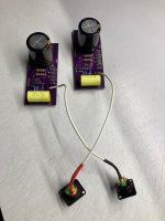
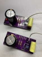
A rainy day soldering project, the beginning of something. My chokes have a DCR of 0R3-0R5 depending on whether I believe the spec or my DVM, so R3 will bear the burden of setting bias. This 3W of 0R75 is just a placeholder until I figure out the power supply & layout. I may do these as monoblocks with the PSU separate, either laptop bricks or a linear supply in a separate box. Early days.
Attachments
A general tip for measuring DC resistance of chokes:
Build a 1 Amp current source (or another convenient value), hook it up to the choke and measure the voltage. A DVM is better at measuring low voltages.
V = IR
Build a 1 Amp current source (or another convenient value), hook it up to the choke and measure the voltage. A DVM is better at measuring low voltages.
V = IR
Another way is to connect a known value resistor in series with the choke in a circuit with a voltage, measure the voltage drops across the resistor and the choke. Calculate the current using the known resistor value and voltage drop. Then calculate the choke DCR using the voltage drop across it and the calculated current.
When I measured my 193V, I used a laptop power supply and a 10W resistor (could have used a 5W resistor) that measured 155R. In series with the 193V and connected to the power supply, the voltage across the resistor was 18.25V and the voltage across the 193V was 0.117V.
155R resistor: I = 18.25V/155R = 0.118A
193V: R = 0.117V/0.118A = 0.992R, very close to the specified 1.0R
Thanks Ben and Tungsten! I am realizing that my chokes have different DCRs too and maybe the differences in bias I observed were due not just because of the devices but because of the chokes too. When I measured their DCRs, the Fluke reported 1.2R for both and my other meters were close. So, I took it that at the very least they are close in value, even though that value may not be 1.0R. I will remeasure and report back.
Meanwhile, there is a way to get higher bias with the 193V, if it doesn't do it by itself. Will post about it tomorrow.
Meanwhile, there is a way to get higher bias with the 193V, if it doesn't do it by itself. Will post about it tomorrow.
Has anyone tried and liked a 48V rail for a SIT follower? I can make a separate box with a 48V linear PS without spending any money, except on connectors.
I built a 2SK180 follower with a power supply which loaded produced about 43V or so (https://www.diyaudio.com/community/threads/mo-chokes-building-2sj28-2sk180-monoblocks.370479/page-3). It is choke loaded with bias voltage at the gate so Vds is about 40V.
Presently, I am working on a 2SK182ES follower with a power supply of about 60V (https://www.diyaudio.com/community/...mer-coupled-vfet-sit-amp-design.372261/page-4). This is also choke (transformer) loaded with bias developed by source resistance. Vds is about 54V.
I have found that with higher Vds on the big Tokin SIT followers, quite low distortion numbers can be achieved with 2nd order harmonic dominating. The 2SK180 follower is my favourite amp, although I haven't properly auditioned my 2SK182ES as it is still under construction.
I think it is worth giving 48V a try. It wouldn't be too hard to breadboard a circuit for testing. A choke loaded follower is pretty simple, especially if you can adjust the bias with the choke resistance and some additional resistors.
Are such power supply experiments for the TDV merely increasing the supply voltage and monitoring bias and temperature, or do other components need adjusting?
- Home
- Amplifiers
- Pass Labs
- Total Domination VFET (TDV) Amp (using 2SK2087C)