Hi Andrew. So, a total value of ~11000uF (2x 22000uF in series) would be enough? I have a couple of 22000uF 16V here that I'm not not using...10V 4700uF caps are small and cheap and you can build a bank of 8 or 10 for little space and little money
8 will give ~9400uF and 10 will give ~11750 uF
This is quite a bit more than the 3400uF that your two 6m8F can give. (the impedance, Xc, of 3400uF @ 50Hz is 0.94ohms)
two 22mF 16V is good.
Calculate the Xc.
Then using the diode maximum voltage for zero bypass current, approximately 400 to 500mVpk for a cold power diode, calculate the AC peak current that can pass through that Xc.
Now make an estimate of the rms current that goes through the amplifier's primary winding and make a further estimate of the peak to rms ratio for the capacitor input filter effect on primary current, it is definitely not a sinewave and therefore not a 1.41:1 ratio.
You discover that when the diodes are not passing that the rms current into the primary needs to be fairly low , even with big DC blocking capacitors.
For small and medium size amplifiers one needs milli-Farad capacitance.
I have never tried a big transformer that is heavily loaded. 1kVA on domestic listening is as big as I have gone.
Thanks guys;
At the risk of redundancy, I have a strong suspicion that it is not a DC causing the noise. The noise level increased, when a microwave oven was used. I plugged the oven into the opposite phase, and the noise still increased.
My assumption was that if there was a DC offset issue, moving the micro from one phase to the other would either add or subtract DC and therefore be reflected by different noise levels. My thought was that it is just noise on the line, causing vibrations in the (windings). Am I completely 'out to lunch' on this?
BTW; David (or anyone I haven't bored to sleep yet):
I have an electrical background, so I will take all safety precautions, but can you suggest a suitable set-up to measure the no load current (secondaries not connected) Yes I have an nice Leader scope and a variac. I suspect that we may be able to determine the line voltage versus saturation point?
Would I use a 1 ohm (or less) resistor as a shunt in the neutral side?
Thanks again Peter
Also, Thanks Andrew;
What would be your suggested cap values for a Blocker that would have a 15 amp capacity? I have not found caps with ripple current ratings (other than 'high').
When calculating the drop across Xc, you can just assume that the current is a 60 Hz sinewave for simplicity and it ends up being conservative. The peak to RMS ratio doesn't really hurt you. The dominant harmonic is the third at 180 Hz, where Xc drops by a factor of 3 so the voltage drop will be less. The caps can handle more ripple current at 180 Hz as well.
If the diodes go into conduction when you're drawing 30A off the mains, who cares? At that point you won't hear any buzz coming off the trafo.
If the diodes go into conduction when you're drawing 30A off the mains, who cares? At that point you won't hear any buzz coming off the trafo.
I have not found caps with ripple current ratings (other than 'high').
You need to look up the spec sheets on the caps. At one time, in printed Digi-Key catalogs, rated ripple current (for either 1000 hours or 5000) was listed for all the Panasonic caps. Now you'll probably need to download a PDF from a particular supplier which should have ripple current and ESR information among other things.
I use 10r in the Neutral. That usually gives me enough resolution using 199.9mVac scale on my voltmeter. A very small transformer might require 20r. A very big transformer will probably require 4r7, particularly when you reach 250Vac and 253Vac. That's when the primary currents starts to become enormous. You don't want the resistor getting hot and ruining your accuracy due to tempco..............
Would I use a 1 ohm (or less) resistor as a shunt in the neutral side?
Thanks again Peter
15Arms is enormous.Also, Thanks Andrew;
What would be your suggested cap values for a Blocker that would have a 15 amp capacity? I have not found caps with ripple current ratings (other than 'high').
That would imply a maximum primary current of at least 45Apk and maybe even approaching 150Apk, when feeding a capacitor input filter.
The diodes will definitely turn ON because that 15Arms load is in effect abuse.
I use a bank of small cheap electrolytics.
Generally 8 to 12 in series/parallel arrangement to give the necessary Xc @ 50Hz for currents around 1Arms.
1Arms allows around 200W to 250W of downstream power consumption and that may result in a primary current of <6Apk
Last edited:
...BTW; David (or anyone I haven't bored to sleep yet):
I have an electrical background, so I will take all safety precautions, but can you suggest a suitable set-up to measure the no load current (secondaries not connected) Yes I have an nice Leader scope and a variac....Would I use a 1 ohm (or less) resistor as a shunt in the neutral simply side?
Yes, that's what I did. A proper current probe is safer but I don't have one and presumably you don't either.
Your transformer probably has a no-load current draw in the order of 100 mA to 200 mA so 1 ohm is a sensible value.
Use the Variac to soft start it. The steady state value may be only 150 mA but the inductive turn on pulse can be >100 AMPS and this will blow a small resistor spectacularly, even if it is quite adequate for the steady state load.
Take safety precautions of course, I was quite pleased I remained careful, because my resistor did not blow on the first test, took a combination of turn off that happened to leave remnant field and turn on at a particular phase.
Your transformer is MUCH more substantial so potentially much more serious pulse.
The non-sinusoidal current waveform is very obvious, doesn't need calculations of current versus volts or a bulb tester.
Actually a bulb tester may mislead you because your transformer is so atypical, probably draws 10 W to 20 W no load.
I suspect many people would interpret that as faulty.
Best wishes
David
Just to be perfectly clear.
Use a substantial power capacity resistor even if you use the variac to soft-start.
The steady-state dissipation is low but you want safety reserve to handle heavy current pulses if there is unexpected transformer saturation.
Last edited:
Just one question: is a DC blocker a good practice to ANY toroid? Otherwise only when noisy or getting hot, right? Thank you again.
The last two Power Amps had a DC block fitted before I even powered up the transformer to find out if it had a problem.
The DC effect is very intermittent in my area. And while it is evident it is not constant. One can hear the quiet growl build and subside over a period of a few seconds.
It would be quite difficult to find which transformers, including Rcore and EI, that are susceptible to the DC effect.
Some manufacturers fit DC block as standard.
I bought 100off 4m7F 10V to replace my stock of 25off 3m3F 16V, that I had nearly used up.
When one is using 12*3m3F for DC block duty for one transformer/amplifier, they don't last long.
Hi Folks;
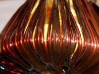
Just a quick update on the 'toroid dipping'. I am learning the hard way, what has been mentioned here; The varnish is reluctant to dry, in the interior of the toroid. After a day of drying at room temp, increasing temp with a portable heater causes the toroid to drip again. I assume remaining solvent is heated, then dissolves through the skin formed on the bottom. On every dip (going for no. 12 soon) I believe interior cavities to be retaining a little more.
Here is a look after 10 dips;
Attachments
I thank everyone for their help so far, but this is clearly taking a ridiculous amount of time.
To keep my self amused in the mean time (my wife won't pose with my toroid anymore, even after explaining that my 'toroid' is part of an amplifier).
I decided to sell a BGW 410 power amp, to make room for new projects. It always had a slight pop as the speaker relay pulled in.
Testing the amp before placing the add, the turn on 'pop' took out a tweeter on one of my 'work horse' Cerwin-Vega PD-18's. Could I once again ask for your guidance with this problem. I will start a thread: BGW 410 turn-on POP.
Thanks again, Peter
Another minor update;
The toroid is going for varnish dip no. 15 this weekend. I am reluctant to do a listen test until the interior cavities are completely filled. I am noticing a more solid sound when I tap on the outer windings, so I remain optimistic.
This thread has tapped the knowledge of a number of very informed people, so I would like to raise another concern. Shortly after purchasing this amplifier, channel B clip light would illuminate and the output for that channel muted (speaker relay stayed in but I believe gain was electronically reduced).
This amplifier was (still is) intimidating to someone with my skill level, so I brought the amp to a shop; Michael Enterprises in Barrie, Ontario. A little 'plug' because the repair tech was very communicative with the repair process and the bill was what I thought extremely fair; $80.00 pls tax.
He mentioned that he replaced several small electrolytics, I believe in the protection circuitry. I would go back, but hesitate because he already spent more hours on this amp than I was charged for.
I have attached the full schematic ( I hope), and ask this: Where is the circuit that monitors clipping and corresponding gain reduction. I would like to learn more about these amplifiers, I think they have a lot of potential, no pun intended!
Thanks again, Peter
Attachments
I have attached the full schematic ( I hope), and ask this: Where is the circuit that monitors clipping and corresponding gain reduction. I would like to learn more about these amplifiers, I think they have a lot of potential, no pun intended!
Thanks again, Peter
You will find the answer if You check page 4!
Sajti
... varnish dip no. 15 this weekend. I am reluctant to do a listen test until the interior cavities are completely filled
...
It is possible to overdo this- any exterior layer of resin will act as a thermal insulator, if it's too thick then temperatures will increase detrimentally.
Probably not a problem for your home use but you may want to consider it, if only as a reason to do a test sooner rather than later.
That would also satisfy everyone's curiosity, don't keep us in suspense.😉
Best wishes
David
This amplifier was (still is) intimidating to someone with my skill level, so I brought the amp to a shop; Michael Enterprises in Barrie, Ontario. A little 'plug' because the repair tech was very communicative with the repair process and the bill was what I thought extremely fair; $80.00 pls tax.
He mentioned that he replaced several small electrolytics, I believe in the protection circuitry. I would go back, but hesitate because he already spent more hours on this amp than I was charged for.
I'd take it back, you paid and he didn't fix it? . when I was a tech I wasn't allowed to remove and replace a single part unless I had pin pointed the exact cause. All the re-work ladies knew about this policy, and there was a "paper trail". We refered to the bad techs as" shot-gunners". Why should you pay by the hour for guys learning on your ticket, doest seem right. Sure there are basket case jobs and others are simple, I reckon basket case jobs need to be re bid based on what is found in 1st hour of troubleshooting. Sounds like he didn't know what he was doing. Ask for a more experienced audio repair tech to take over, unless you enjoy the "phone chats" more.haha BTW I always ask for replaced parts back on any repair job.
Last edited:
Varnish will conduct heat more effectively, than layers of trapped air.It is possible to overdo this- any exterior layer of resin will act as a thermal insulator, if it's too thick then temperatures will increase detrimentally.
Probably not a problem for your home use but you may want to consider it, if only as a reason to do a test sooner rather than later.
That would also satisfy everyone's curiosity, don't keep us in suspense.😉
Best wishes
David
Varnish will conduct heat more effectively, than layers of trapped air.
The resin manufacturers claim that the transformer is better off internally with resin than air pockets.
Seems plausible but I've never seen any actual data on this (I'd like to see it if you have any?).
But an external overcoat of resin will impede the transfer of the heat to the air to be dissipated by convection.
That's why I specifically wrote "exterior layer of resin" and only a possibility if "overdo[ne]"
Best wishes
David
agreed, trapped air is an excellent heat insulatorVarnish will conduct heat more effectively, than layers of trapped air.
but that's yet another reason dipping XFMRs isn't effective, it doesn't remove hardly any of the trapped air. One must use a vacuum to remove the air so the viscous liquid can replace it..
The resin manufacturers claim that the transformer is better off internally with resin than air pockets.
Seems plausible but I've never seen any actual data on this (I'd like to see it if you have any?).
But an external overcoat of resin will impede the transfer of the heat to the air to be dissipated by convection.
That's why I specifically wrote "exterior layer of resin" and only a possibility if "overdo[ne]"
Best wishes
David
convection cooling a xfmr is delta T combined with surface area and air flow. any surface coatings don't come into play here. black body radiation helps maybe 5% in still air.
Hi Guys;
I'm glad to see that this thread has not yet put everyone to sleep! Thanks so much for all the input.
Thanks sajti;
I had a suspicion that the problem was on page 4. I see that there is a 17 pin connector on this page and the same 17 pins on page 6, output section. I assume that this is the board that is 'piggy-backed' on the output modules. Page 4 is called Pre-Amp, and yet it seems to be mostly protection circuits. Could you point me to an area on page 4 that would cause the clip light to stay on, and have the volume muted, even with no signal, or could it be any number of areas? This problem was intermittent at first.
What is the likelihood of an (electrolytic) cap causing an intermittent problem? In my limited experience, when a problem comes and goes, it is usually a bad connection, although I did tap on all the connectors I could reach, particularly the 17 pin piggy-back area.
Hi David;
Thanks for raising the concern regarding over-insulating the transformer. Just to be argumentative, it was suggested at one point that I have the toroid epoxy potted. This would have almost certainly caused clearance problems, in addition to, as you point out, thermal issues. Are (high)power transformers ever potted?
Please have a little more patience. On the last dip, I observed less 'dribbling' when I applied heat from a portable heater. Prior to this I saw dripping when trapped solvent was warmed and then dissolved its way to the bottom. Another reason for delaying; I have to be convinced that it a solid block of varnish, it is my way of preparing for failure! I'm a pessimist and I don't want to think; "Maybe another couple of dips would have done it.." Also regarding the thermal issue, there is a sensor inside the transformer windings which will open the speaker relays, and if this becomes a problem, the varnish seems to be easily removed with solvent.
Hi infinia;
The tech actually repaired the amp. I just don't feel right about going back for 'free training' when the bill was so reasonable. $80.00 Canadian, isn't that about 25 bucks American, by now? I just want to learn about these amps because the specs look on paper, they look well built on the inside, IMHO, and made in USA! I hope to buy more as people get tired of lugging these 80 pound monsters and go to these (horrible) class D light-weights.
- Status
- Not open for further replies.
- Home
- Amplifiers
- Solid State
- Toroidal Transformer Noise