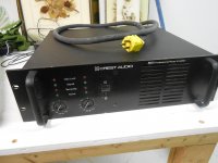
Here's what I picked up on the weekend; Yamaha P2201 and a Crest 8001, both purchased 'not working'.
I may have the classiest doorstops, north of Toronto!
Re; the Yamaha, seller claimed one channel may work.. Power switched removed, not bypassed, one side has no output transistors..smells like burned resistors and cigarettes, but I own a P2200 (with meters) and think that it is worth restoring.
The Crest, well I'm a sucker for punishment and couldn't resist. Maybe I will learn something.
Attachments

Had an idea I would like to check.
The suspicion is that the transformer is a bit close to saturation, so what is it rated at (VA) and what mass?
I hope you put it on the scales before you soaked it, to check how much varnish it absorbed.
Or could you put it on now and estimate how much varnish has been added?
If you can't put it on a scale then could you please measure the outside dimensions?
Best wishes
David
Hi Dave;
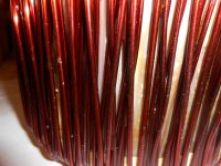
It's been 24 hours since 'dip 6'. There was still considerable bubbling for about 10 minutes. As mentioned, I limited the submersion to 15 minutes to avoid dissolving previous layers. I am starting to see a buildup of varnish on the windings. I'll take another picture after dip 7.
At this point, the toroid weighs 31.0 pounds, and is 6 & 5/8 inches dia. and 4 & 5/8 inches tall. I doubt that the weight has increased significantly with the varnish. I have added 2 or 3 ounces ( 100 cc or so, very approx) 3 times, to my dipping 'tank', but there has been volume loss from solvent evaporation (so I have been told) and dripping.
To continue the debate about the interior remaining 'a sticky mess'. I would argue that if I left the lid off, a bottle of this product would first develop a skin but would eventually harden completely through, as the solvent (migrates) through the hardened layer. This is just my theory, but I doubt that the interior would remain liquid forever. I believe that sealing the outside with plastic (mylar) film will prevent the release of the last remnants of solvent.
Thanks again for your input, Peter
The Mylar strip will leave gaps that will allow the solvent vapour to escape.
The strip on strip layers are not gas tight.
Have you tried baking the transformer before immersion? Maybe 100°C or a touch higher. The air inside the transformer will be warm and will contract in the presence of the cooler varnish and help suck the varnish into the interior.
The strip on strip layers are not gas tight.
Have you tried baking the transformer before immersion? Maybe 100°C or a touch higher. The air inside the transformer will be warm and will contract in the presence of the cooler varnish and help suck the varnish into the interior.
Thanks for the data.
Lower flux density inevitably makes a transformer heavier and 14 kg is already one hefty transformer, so I understand why they may have been constrained to accept a bit of noise.
All a question of "eventually", some old paint has a thickish skin but runny centre even after the lid has been left off for quite a while.
But all a moot point now, we do better than speculate, we have an experiment!
People miss so much when they say it's dull "to watch paint dry"😉
In anticipation
David
Lower flux density inevitably makes a transformer heavier and 14 kg is already one hefty transformer, so I understand why they may have been constrained to accept a bit of noise.
...if I left the lid off, a bottle of this product would first develop a skin but would eventually harden completely
All a question of "eventually", some old paint has a thickish skin but runny centre even after the lid has been left off for quite a while.
But all a moot point now, we do better than speculate, we have an experiment!
People miss so much when they say it's dull "to watch paint dry"😉
In anticipation
David
The "Paint drying drama";
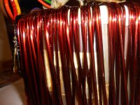
Attached are results after dip 7. I see small filets developing between the wires, but far from what I feel is sufficient. I am now suspecting that even shorter submersion times are required to prevent removal of previous layers. Dip 8 will be timed to 5 minutes.
I am trying to achieve a 'potted' effect with a varnish, rather than an epoxy, yes I know that it was suggested. However, I believe I can eat this elephant, one fork at a time.
Thanks, Andrew, the toroid has been spending about 24 hours in front of a portable electric heater before dips. My guess is that the transformer is about 50 C. my concerns are for the external wiring and connectors which I did not want to remove. About the mylar film; I would have to wrap the toroid in something wider, I suspect, because it must be wound around the circumference. The centre is plugged by epoxy, not allowing toroidal wrapping.
To keep myself amused 'while the paint dries', I have started to tinker with a dead Yamaha P2201. For the sake of organization, I will start a new thread for that amp, and at the same time, continue to update this thread when there are interesting developments. I am extremely grateful for all the helpful advice I have had from everyone so far, and hope very much that I could get you support for my latest project.
I will call the new thread "Yamaha P2201 rescued from the scrap heap"
Attachments
You have to get that central plug removed. The insulation wraps around the toroid in the same manner as you see for the secondary windings.............. About the mylar film; I would have to wrap the toroid in something wider, I suspect, because it must be wound around the circumference.
You can add an extra layer or two around the perimeter but this not required except when adding a belly band. You could use 25mm or 50mm wide for this extra insulation.
The centre is plugged by epoxy, not allowing toroidal wrapping........
...between the wires, but far from what I feel is sufficient...
Practically all of the noise should be from the core so further effort to coat the wires may be unnecessary.
Can you just run the disconnected transformer on no load to check if there's been any improvement?
Maybe save yourself some time and effort.
Best wishes
David
Thanks again Andrew;
I am afraid I have committed to this dipping project and thought that the removing the centre epoxy plug without damaging the windings was beyond my talents and patience.
David;
It is with great willpower ( and fear of disappointment) that I have simply not put the AC to primary, to observe any improvements.
My reasons are as follows:
In a past career, I was an IMAX film projector installer. These machines were extremely noisy, but as long as the projection booth was sealed airtight from the theatre, noise was suppressed. I wish to continue dipping to the point that there is a substantial shell coating the transformer. If I have not damped the internal noise source, I would at least like to contain it.
Far fetched theory no. 2; The toroid is supported by the center epoxy/nylon plug. My excuse to Andrew for not removing it, is it's very solid attachment to the inside of the windings. I am desperately clinging to the hope that if the noise was from the core lamination, it would probably be transmitted to the center mounting plug. My stethoscope probing found the wires only, to be the source of noise.
One more reason to drag out the "moment of truth"; Dip 8 was limited to 5 minutes and I see a noticeable increase in varnish thickness on the wires. It seems that my extended dip times were remove much of the previous deposits. In any case, I am glad that the first dip was 24 hours. I'm also glad I have a 'day job'. In an attempt to be scientific, I tried measuring the 'before' noise level but my Radio Shack SPL meter would not yield any meaningful readings. The results of all this effort will be judged subjectively, so I don't want to blur my comparisons with an intermediate test.
...noise was suppressed...If I have not damped the internal noise source, I would at least like to contain it.
Yes, I have had a similar idea.
Lower flux density in the transformer should be quieter but is quite expensive, so maybe just mount the transformer in a noise enclosure.
That's essentially what they do with industrial transformers, question is how to stop noise transmission but keep heat dissipation. Hmm.
Maybe a damped aluminium base plate and cover.
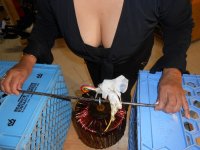
The photo with your wife is not only very cute but also a useful illustration of the size and proportions of the transformer too... is it's very solid attachment to the inside...
Makes it clear why it would be difficult to remove the core.
Despite the tranny's size it is still small for the 5000 W in the amp's specification sheet.
Increases the suspicion that it's run close to, or at saturation.
Would be educational to look at the no-load primary current waveform on an oscilloscope.
You have one I think, maybe when you do your noise test?
Best wishes
David
Nearly.
You don't need 63V capacitors.
The Diode bridge limits the maximum overload voltage to 2times Vf and that rarely, if ever, exceeds 3Vpk.
A 6V capacitor would do.
10V 4700uF caps are small and cheap and you can build a bank of 8 or 10 for little space and little money
8 will give ~9400uF and 10 will give ~11750 uF
This is quite a bit more than the 3400uF that your two 6m8F can give. (the impedance, Xc, of 3400uF @ 50Hz is 0.94ohms)
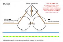
I do like the note on the left referring to the effect of the soft start current limiter.
The starting of the transformer is one of the overload conditions that could take the diodes into conduction.
Normally, we do not want the diodes to conduct.
You don't need 63V capacitors.
The Diode bridge limits the maximum overload voltage to 2times Vf and that rarely, if ever, exceeds 3Vpk.
A 6V capacitor would do.
10V 4700uF caps are small and cheap and you can build a bank of 8 or 10 for little space and little money
8 will give ~9400uF and 10 will give ~11750 uF
This is quite a bit more than the 3400uF that your two 6m8F can give. (the impedance, Xc, of 3400uF @ 50Hz is 0.94ohms)
I do like the note on the left referring to the effect of the soft start current limiter.
The starting of the transformer is one of the overload conditions that could take the diodes into conduction.
Normally, we do not want the diodes to conduct.
Last edited:
Is this also a better solution for RFI, instead of a 0.01uF cap across trafo's primary? Thank you.Anyone built one of these?

No.
This is a DC block to help reduce transformer saturation, or near saturation, due to unequal waveform that makes the transformer draw excessive primary current and usually becoming noisy (a growl).
And the DC block does not need to be in the Hot/Live line.
It works just as well in the Neutral Line and even works between the two windings of a series connected dual primary.
The slight advantage of locating the DC block in the Neutral is that it operates at near Neutral voltage. The voltage difference between the Chassis and the DC block is much lower (when the mains socket outlet is wired correctly).
Last edited:
Hi Guys;
In the earlier pages of this thread, the DC blockers were discussed at some length. I did build this circuit, but I connected the caps in parallel ( polarities reversed ) as in the Bryston amps.
With my limited knowledge, I would have assumed that the above cap configuration was 'legal' and the parallel connection was a no-no....Why does (did) Bryston do it?..In parallel, the electrolytics are exposed to reverse polarity, although I think, limited to 2 times the diode forward conduction V drop of the diodes.
To be honest, the parallel cap connection had no effect on my transformer noise. I foolishly did not try the above series connection. If my 'varnish dipping' is unsuccessful, I will try the above configuration, but I thought it was a safe bet to copy Bryston.
Thanks again, Peter
From all the various descriptions, I am fairly convinced your transformer is more troubled with too high a primary voltage.
If this is the case, then damping the secondary turns and adding a DC blocker will not solve that.
The only solution that I am aware of is to add primary Turns. But that plug in the middle stops that experiment dead !
You could plot a Primary Current vs Primary Voltage curve for your transformer.
That would tell the experts here whether insufficient turns is the problem.
Last edited:
Or just plug your trafo in through a dim bulb limiter. If it's too far into saturation, the bulb will glow orange. Typical magnetization current will be low enough for it to stay dark.
I built a couple amps of similar power level, using 3 trafos to generate the rail voltages (46, 92 and 138V). The original primaries were for 100V, 50 Hz, 1024VA each. All three together on 120V 60 Hz and the bulb stays dark. No hum or buzz. I have some similar trafos with 115V 60 Hz primaries and the bulb glows and they make noise. I didn't use those, even though they were a better form factor and easier to rewind.
It won't really hurt anything to run them a bit into saturation - other than a bit of core loss and potential noise. Battery charger trafos and HID lamp ballasts are run way up the BH curve and last for years at full power. Loud enough to wake the dead - and that's how you know they're still working.
- Status
- Not open for further replies.
- Home
- Amplifiers
- Solid State
- Toroidal Transformer Noise