Again
ATL DC Blocker diagram with letters:
Again
Aleksandar tells me:
ATL DC Blocker diagram with letters:
Again
Aleksandar tells me:
33 Ohm resistor works at the moments of capacitors charging/discharging. Of course schematic can work without it but I think it worth staying there. It cannot defeat schematics normal work since it's impedance is much larger than capacitors impedance at 50/60 Hz.
About pins - pin 1 (L) at the input is schematic's input. It travels through the filter and ends at the Output pin 3. Input Pin 2 goes directly to the Output pin 2 (GND). Input pin 3 goes directly to the output pin 1 (N). You can see this on the PCB:
Last edited:
10M will let through less DC than 33r and still discharge any residual change on the capacitors after switch off.
Maybe...
-> https://en.wikipedia.org/wiki/Electric_shock
33 Ohm << 1750/1200/1000 - 6100 Ohm
-> https://en.wikipedia.org/wiki/Electric_shock
The International Electrotechnical Commission gives the following values for the total body impedance of a hand to hand circuit for dry skin, large contact areas, 50 Hz AC currents (the columns contain the distribution of the impedance in the population percentile; for example at 100 V 50% of the population had an impedance of 1875Ω or less):[16]
Voltage 5% 50% 95%
25 V 1,750 Ω 3,250 Ω 6,100 Ω
100 V 1,200 Ω 1,875 Ω 3,200 Ω
220 V 1,000 Ω 1,350 Ω 2,125 Ω
1000 V 700 Ω 1,050 Ω 1,500 Ω
33 Ohm << 1750/1200/1000 - 6100 Ohm
Last edited:
This resistor is absolutely unnecessary. What could happen? The caps could be charged to 1-2 volts depending of used diodes/zeners. Not very dangerous I would say.
For goodness sake, if the transformer is buzzing just add a choke in series with the primary to drop the voltage across the primary. If there's DC on the mains, the fix is simple - use a DC blocker.
Job done.
Job done.
DC Transformer Saturation
cliftonlaboratories.com DC Transformer Saturation
cliftonlaboratories.com DC Transformer Saturation
PWB1010-L Frequency Response with DC Current
...
However, even modest amounts of DC current significantly reduce the low frequency response as reflected in the plot below. (The test setup I used to inject DC current into the PWB1010 causes about a 1 dB insertion loss regardless of frequency.)
At 50 mA DC current, for example, the -3 dB response is increased to 300 KHz or more. Or, looked at another way, 50 mA DC current increases the loss at 10 KHz from 0.5 dB to nearly 35 dB.
An externally hosted image should be here but it was not working when we last tested it.
Last edited:
Low ESR and ripple current rating
http://www.illinoiscapacitor.com/pdf/Papers/applications.pdf
http://www.illinoiscapacitor.com/pdf/Papers/applications.pdf
FILTERING:
A filter capacitor is used to smooth the DC pulses after rectification. The capacitors store charge and deliver it to the load when the rectified or pulsating DC voltage decreases below the peak of the DC voltage signal.
The major capacitor characteristics are capacitance, ESR, and ripple current rating.
Hi Guys
The usual DC blocker uses an integrated bridge as these have high current ratings and modern ones have easily soldered leads. Join the DCs together. Join the ACs together. Now you have two diodes in parallel for each direction, all in parallel. Your 25A bridge has now become a 50A bilateral clamp.
Now you get the highest-value electrolytics you can find and wire them anti-parallel across the bridge ACs to Dcs. Typically a pair of 33mF 6V caps is fine for the largest toroids.
The diodes clamp the voltage across the caps. The caps conduct the AC current under normal operation. The clamp voltage is <1V, much better than series diodes.
Ideally there would be a current limiter of some sort to protect the DC blocker and the PT.
Have fun
AV Marantz SR4500 with ATL Hi-Fi DC & Ripple Blocker x4 ME
Capacitors burning
With only two hours of capacitors burning: the sound is “50% better” than with only DCB x2.
In DCBx2 the sound was changing for about three weeks. Sometimes I noticed that the sound worse. Disconnected / discharged capacitors and I had a great sound again.
Remember: 8 x 18000 microF 105 ºC !!!
With only two hours of capacitors burning: the sound is “50% better” than with only DCB x2.
In DCBx2 the sound was changing for about three weeks. Sometimes I noticed that the sound worse. Disconnected / discharged capacitors and I had a great sound again.
Remember: 8 x 18000 microF 105 ºC !!!
ATL-Hi-Fi DC & Ripple Blocker x4 ME => AV Marantz SR4500 with KEF Q100 (bass-reflex closed) and ifi iCAN.

Hi Maty;
I have tested my amp with a variac and found it to be quiet when the line voltage was reduced. Is is possible that by stringing multiple 'DC Blockers' in a chain, you are simply reducing the line voltage?
I would like to ask anyone; Is it possible to measure DC offset on the line? I envision a simple half wave (one diode) charging a capacitor. A second diode configured to charge a second cap from the other half of the line sine wave. Could one just compare the voltages across both capacitors?
It may be obvious at this point that I am hell-bent to dip the toroid in something to 'lock up' the vibrating windings. I have acquired about 4 litres of Electrical Grade Varnish and had a tour of a large motor and transformer rewinding facility. It was explained that this varnish will air dry in 24 hours (accelerated by heat). Also vacuum impregnation is equivalent to approximately 7 dips at atmosphere... So I will dip it 7 times.
I will keep you all posted on my progress, and please feel free to reply at any time. I appreciate any help, I would hate to mess up an otherwise 'knock out' amp.
Yes. Tomorrow I will measure voltage at the input and the output. AC and DC.Is it possible that by stringing multiple 'DC Blockers' in a chain, you are simply reducing the line voltage?
Tha is one of the reasons to postpone the variac.
< 235V the AV Marantz sound is very good. Usually I measure 236V-238V at mains before 20 pm. And > 2 Vdc !!!
Your situation is much worse than mine in terms of stress. You need to bring it down to a more reasonable value, and the best is a good variac to connect all your home stereo, not just the amplifier.
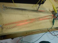
Pictured is my dummy load; Electric Clothes Dryer element. I thought I would test the amp before I went to all the trouble of treating the toroid.
1160 Watts per channel into 8 ohms. Nice!
Was that 8 ohms cold, or 8 ohms hot? It makes a difference. I guess you can adjust it on the fly if you need to.
Hi wg ski;
I was prepared for the resistance to change (increase) as the element got hot. I set the yellow alligator clip to bypass enough of the element to bring it to 7.4 ohms cold. Almost impossible to measure the resistance when it is red hot. I saw about 94 Volts measured by my fluke meter, before I saw clipping on the scope. It could do this immediately, not just when the element started to glow. Would you agree that this is a fair test?
I am starting to like this amp. At the risk of sounding like these audio fanatics that compare speaker cables, I think this amp has incredibly more punch than my Phase Linear 700's. I may get banned from the Phoenix Forum for saying that.
- Status
- Not open for further replies.
- Home
- Amplifiers
- Solid State
- Toroidal Transformer Noise