Hi tauro0221;
I saw the soft start circuit on my schematic, I will check for voltage drop across the relay contacts. Is this a common problem with these big amps? Could that cause the toroid to buzz? Also; What is an NTC? I thought they were just power resistors.
I saw the soft start circuit on my schematic, I will check for voltage drop across the relay contacts. Is this a common problem with these big amps? Could that cause the toroid to buzz? Also; What is an NTC? I thought they were just power resistors.
Hi,
Sorry, I should explained it. They are NTC Thermistors =a component which resistance decreases with increasing temperature, and the device is called a negative temperature coefficient (NTC) thermistor.
Sorry, I should explained it. They are NTC Thermistors =a component which resistance decreases with increasing temperature, and the device is called a negative temperature coefficient (NTC) thermistor.
...Also vacuum impregnation is equivalent to approximately 7 dips at atmosphere... So I will dip it 7 times...
Varnish is usually used to protect the transformer or motor coils from moisture, contamination and improved resistance to electrical field effects like corona.
Simple dip is adequate for all these improvements.
But to suppress noise you need to immobilize all the coils, so you need to be sure the resin/varnish infuses all the way in.
Vacuum is practically certain to be better at this.
If you just simple dip then any extra dips will just build up extra varnish on the outside. Fine for typical requirements but not ideal for yours.
Normally I would recommend to try the easy option and if it's not adequate then pay the extra for the premium solution.
But in this case, once the transformer is dipped then it will be ineffective to try to vacuum infuse, any air spaces will be surrounded by dried varnish and inaccessible.
So I really think a vacuum is the way to do it for you.
Composite fabricators and even some woodworkers use vacuum to infuse resin for laminates.
Can you try them?
In any case, curious to learn how it works out and look forward to your results.
Best wishes
David
The transformer has too few turns for the voltage you have..................... I have tested my amp with a variac and found it to be quiet when the line voltage was reduced. ....................
You need to add more primary turns or reduce your mains voltage using an autotransformer.
A toroid transformer with an open centre is fairly easy to modify to add primary Turns.
BUT !!!!!!
those primary turns will be on the OUTSIDE and you MUST protect yourself from risk of electric shock.
you can monitor the current using an accurate low resistance in series with your load. Monitor the Vdrop of both the resistance wire heater and the Vdrop of the current measuring resistor.Hi wg ski;
I was prepared for the resistance to change (increase) as the element got hot. I set the yellow alligator clip to bypass enough of the element to bring it to 7.4 ohms cold. Almost impossible to measure the resistance when it is red hot. I saw about 94 Volts measured by my fluke meter, before I saw clipping on the scope. It could do this immediately, not just when the element started to glow. Would you agree that this is a fair test?
I am starting to like this amp. At the risk of sounding like these audio fanatics that compare speaker cables, I think this amp has incredibly more punch than my Phase Linear 700's. I may get banned from the Phoenix Forum for saying that.
if your resistance wire heater is 8ohms and you use a 0r1 current measuring resistor then the heat in the two resistances will be in the ratio of 8:0.1 = 80:1
Use two 0r1 in parallel for 160:1 and that gets the heat in one of the parallel resistances down to 1/320th of the heat in the heater wire.
Your "test" is flawed. It is not a fair way to arrive at any conclusions, except your conclusion that the wire ran hot !
Your carefully measured 8r0 dummy load was probably nearer 12r
Yes - you really have to measure voltage and current. I would have started with a resistance of 5 to 6 ohms. Even the big "dog bone" 225W resistors heat up and change. You have to immerse them in oil or icewater to get them to stabilize for this sort of test. Even then the duration has to be short. Water heater elements are good too - because icewater is easy. But you would need to construct a series parallel bank to be able to tune your resistance value.
It's no surprise it has more punch than a PL700. I can run a labhorn of each channel and the speakers cry uncle before the amps do. Try that with a a Flame Linear and you get well, flames.
As far as adding primary turns on the outside of a toroid - I use #12 THHN, solid core. The insulation is thin and tough, and you generally only need a few turns.
Attachments
After Marshall.But............It goes to Eleven
Did you see the (too) short documentary about the development of his amplifiers?
Thanks Guys
Just kidding Andrew, but thanks for advice re; properly testing power output. I have to confess that when I bought the amp used, it had a problem. One channel would mute and the clip light would come on. Strangely, it performed fine when I tested it at the seller's house. Anyway, this repair was beyond my abilities, and a local pro sound and lighting shop repaired it for $80.00.
Thank you: "Michael Enterprises" in Barrie, Ontario, Canada.
The test was to assure me that the bugs have been worked out of the amp. Adding windings is not an option. The center is epoxy filled and I cannot increase the dimensions of the tranny. Also, for the sake of argument, would this not decrease the secondary voltages? My limited research has shown that ideally, the primary should be on the inside.
Dave Zan, I understand that dipping will defeat the effectiveness of any future attempt to vacuum impregnate the trans. As mentioned, there are 16 wires with connectors that appear impossible to remove non-destructively. With your point in mind, the outside of the toroid is wrapped in tape, then the centre was filled with epoxy. I feel that this tape will impede my 'non vacuum' dipping effectiveness. I have an inclination to remove some of this tape to allow penetration of the vanish. I am concerned that the tape is holding the temperature sensor and various wire splices in place. I am planning to possibly remove a few strategically located wraps to allow the varnish in.
I know I am asking you all to 'micro manage' my project, but am grateful for all the help. If I mess up this toroid, it would probably cost more to replace than what I paid for the amp.
removing the outer tape will expose some or maybe all of the secondary windings.
That would allow more effective injection of transformer resin into the secondary.
But if the majority of the noise is from the core and/or the primary, your attempts to silence the secondary will fail.
I warned about that way back in post73
That would allow more effective injection of transformer resin into the secondary.
But if the majority of the noise is from the core and/or the primary, your attempts to silence the secondary will fail.
I warned about that way back in post73
Last edited:
Hi Andrew;
Do you have a link to this video? I remember something about Jimmy Hendrix having his amps modified to the point that the plates in the output tubes would glow red.
Do you have a link to this video? I remember something about Jimmy Hendrix having his amps modified to the point that the plates in the output tubes would glow red.
Hi wg ski;
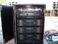
Is that your rack of CA-18's? Have you had any other issues or concerns with these amps? I almost bought a QSC 5050, similar power, but the Crest had better S/N and damping factor specs
Is that your rack of CA-18's? Have you had any other issues or concerns with these amps? I almost bought a QSC 5050, similar power, but the Crest had better S/N and damping factor specs
The other amp in there is a 5050. Not as much real world power as the CA18. But if I'm running all 8 subs I power taper the outers anyway.
I got them used from a touring sound company that was modernizing. Seller said they had the techs go through them, more than likely replacing the problematic small electrolytics in the supervisor circuits. That (and fans getting noisy) is all that ever seems to go wrong with them. Easy fixes - that's probably why your tech only charged $80 instead of 800.
I got them used from a touring sound company that was modernizing. Seller said they had the techs go through them, more than likely replacing the problematic small electrolytics in the supervisor circuits. That (and fans getting noisy) is all that ever seems to go wrong with them. Easy fixes - that's probably why your tech only charged $80 instead of 800.
Thanks, wg ski;
That sounds like exactly what the repair tech was saying, some small caps. He replaced caps in both channels to be safe. I had an issue with the clip light on one channel coming on and that channel muting. Is that what you mean by 'supervisor circuit'?
If and when you have time, would it be possible to show me where that is? I will repost the schematic
Attachments
PS; When I overloaded the input (with level controls set low), the clip lights came on, but when I did my power test and ran the output to clipping, the lights did not come on. I did not push it hard into clipping, just enough to see flats on the sine wave, then backed off the signal and read the voltage. Is the output not monitored for clipping?
Hello All
I think that you are missing the problem. Toroid transformers are much different than other types of transformers. They do not have an AIR GAP. Slight amount of DC on the windings will cause several problems, BUZZ NOISE is one.
A good designed power supply using a Toroid will NEVER USE A HALF WAVE RECTIFIER CIRCUIT? This will bias up the core and buzz / mechanical noise will happen. If the half wave rectifier is a large amount of power the primary input power will skyrocket and the fuse / circuit breaker will open.
You may have a bad rectifier in the bridge circuit. Get out the scope and look @ the rectified P2P ripple are the balanced?
The Varnish vacuum impregnation is also a suspect, however I would not think so @ idle (no signal).
Good hunting
Duke.
It was on BBC iPlayer.Hi Andrew;
Do you have a link to this video? I remember something about Jimmy Hendrix having his amps modified to the point that the plates in the output tubes would glow red.
It might be on YouTube.
Hi Folks, just an update;
Thanks Duke and everyone. To be honest, I have not tested the diodes in the Crest power supply. Both channels produced a clean sine at well over 1000 Watts each, my uneducated opinion is that power supply is OK.
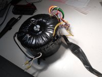
I removed the transformer from the amp, attached a line cord and..... same noise.
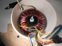
The toroid has an out wrapping of steel sheet, which just slips off, same buzz with or without.
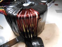
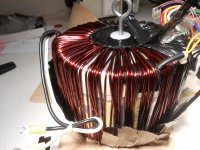
As I started peeling the outer layers of plastic film, I could not help thinking this is the 'beginning of the end', particularly after seeing another layer of plastic below the outer windings. Not having experience with toroids, I was surprised to see the windings are simply wound, not dipped. I am puzzled that a transformer of this power rating would stay together, never mind noise free, without locking the windings together.
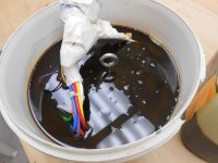
I am encouraged again; after submersing in electrical grade varnish, there was considerable bubbling, leading me to believe that the varnish penetrating internally. I am letting the toroid soak in the bucket (covered) overnight, as mentioned, the first dip is the most important. Tomorrow, I will remove it, allow it to air dry in a warm area for 24 hours. The second dip will not be soaked as long, I suspect a tendency to dissolve the first layer. I plan to repeat this seven times. Ridiculous, but I will report honestly about the noise reduction.
Thanks Duke and everyone. To be honest, I have not tested the diodes in the Crest power supply. Both channels produced a clean sine at well over 1000 Watts each, my uneducated opinion is that power supply is OK.
I removed the transformer from the amp, attached a line cord and..... same noise.
The toroid has an out wrapping of steel sheet, which just slips off, same buzz with or without.
As I started peeling the outer layers of plastic film, I could not help thinking this is the 'beginning of the end', particularly after seeing another layer of plastic below the outer windings. Not having experience with toroids, I was surprised to see the windings are simply wound, not dipped. I am puzzled that a transformer of this power rating would stay together, never mind noise free, without locking the windings together.
I am encouraged again; after submersing in electrical grade varnish, there was considerable bubbling, leading me to believe that the varnish penetrating internally. I am letting the toroid soak in the bucket (covered) overnight, as mentioned, the first dip is the most important. Tomorrow, I will remove it, allow it to air dry in a warm area for 24 hours. The second dip will not be soaked as long, I suspect a tendency to dissolve the first layer. I plan to repeat this seven times. Ridiculous, but I will report honestly about the noise reduction.
Attachments
- Status
- Not open for further replies.
- Home
- Amplifiers
- Solid State
- Toroidal Transformer Noise