A core size of 1" by 2" cannot be a 1kVA transformer.
Assuming a flux of 1T you get ~120VA, at 1.5T ~180VA.
Maybe you could run it @ 1.8T and get at the most 225VA.
Tony,
could you check my numbers?
I design and wind (commercially) my own transformers, and besides "standard" calculations, have experimented a lot both how does real, "over the counter" iron work, and how much can it be abused without danger.
Start by saying than modern commercial iron is very good.
Don't design toroids but conventional EI types, but iron is iron, so my experiences should hold water, at least from the magnetic point of view.
My practical rule of thumb (which works in practice) is, for 50 Hz mains:
Usable V.A.= (core area^2)*1.5 , measuring in centimeters.
So in this case, and *supposing* the core is 2.5 x 5 cm ,
Usable V.A.= (2.5 x 5)^2 x 1.5= 235 V.A. *TOPS* , which perfectly agrees with AndrewT's calculation.
The advantage of toroids over my old technology EI lies in the huge "window" available and the long magnetic core circumference, both of which allow for much lower copper resistance.
In fact I have carefully measured magnetic and resistive losses, and even in my "abused" designs, resistive is still much higher than magnetic, which tells me I am not yet *that* close to the edge of the cliff.
But enough is enough.
Back to that toroid, it would be suitable for an around 150W RMS amplifier, no more.
Which is probably the real output of the "1000W" amplifier it came from 😉
thanks for chiming in, this thread welcomes your expertise.....
while i do built my own traffos for my projects, i am still basically a hobbyist, no intention to go commercial......
my other rule of thumb, when in doubt, treat irons as low grade if you don't know its origins, unless the laminates are 0.35mm thick and is striped....
building one and testing one ... if I ever get that far ha ha
still trying to get my head around all the formulas .. Pat Turner I think uses a very low B figure and that would mean his transformers are much bigger, almost like he is designing them for mild steel ?
so the 300 figure in his formula is probably too big by a factor of up to three
thanks
for my first opt build, i used the one designed by YvesM, i used it for my 6LU8 pp amp, i used 0.35mm thick RM18 laminates.....
one oldtimer fell in love with the sound of the amp that he came to the house 3 times, each time asking to hear the amp, he then went home with amp in hand...
what is said of designing OPT's, it is more an art than a science...
the Wolpert book gives design examples which you can use to make your own..math is easier to follow, imho....😀
Yes, you are right.
The iron I speak of as being "very good" is, of course, bought from a reputable Industrial supplier, and yes, *that* one can be trusted.
Now, if you buy from an unknown small supplier, he *might* have bought the cheapest he found.
I forgot: if you are recycling some old transformer of course design as if it were the cheapest iron.
I can't choose "brands", it's whatever is in the last container they opened, (all good of course or they lose important customers) but i get basically 3 types:
1) a bright greenish/yellowish striped material, same as found in Soldano transformers, some claim it's Russian silicon steel.
2) a 2 tone grey striped material , origin unknown (fir me), still very good.
3) a flat gray Brazilian type.
The only one which comes pre-cut and packaged in 20Kg cardboard boxes.
All others are imported as huge ¿5 Ton? rolls and are cut to size in Argentina.
Which is good because I can order special sized strips to build huge "semi-toroidal" transformers if pressed for space.
Anyway I am experimenting with SMPS to reduce weight (and some cost).
hi tony, the primary winding is 220 turns, gauge 0.7 mm and the secondary is 290 turns guage 1.0 mm.
JMFahey,
yep
OK, I'll grab my son's camera and shoot some laminations 🙂
hi tony, the primary winding is 220 turns, gauge 0.7 mm and the secondary is 290 turns guage 1.0 mm.
hmmm, is that a step up traffo? there are more secondary turns than primary ones...
Yes, you are right.
The iron I speak of as being "very good" is, of course, bought from a reputable Industrial supplier, and yes, *that* one can be trusted.
Now, if you buy from an unknown small supplier, he *might* have bought the cheapest he found.
I forgot: if you are recycling some old transformer of course design as if it were the cheapest iron.
I can't choose "brands", it's whatever is in the last container they opened, (all good of course or they lose important customers) but i get basically 3 types:
1) a bright greenish/yellowish striped material, same as found in Soldano transformers, some claim it's Russian silicon steel.
2) a 2 tone grey striped material , origin unknown (fir me), still very good.
3) a flat gray Brazilian type.
The only one which comes pre-cut and packaged in 20Kg cardboard boxes.
All others are imported as huge ¿5 Ton? rolls and are cut to size in Argentina.
Which is good because I can order special sized strips to build huge "semi-toroidal" transformers if pressed for space.
Anyway I am experimenting with SMPS to reduce weight (and some cost).
i worked 6 years in Russia and the Russian traffos that i saw do not look like the EI one's coming out of the states....and mostly split C cores types.....
the "2 tone grey striped material", gauge 29, i consider these as first class, but nowadays very hard to find in the surplus market, in the 70's they were plentiful and cheap, i was using them for power traffos...
new cores here are imports from Taiwan as i was told, gauge 24, or 0,5mm, very low quality, surprisingly, they sound good in guitar amps...use them in power traffos and they heat up fast and real hot, so that using them entailed oversizing cores an having more turns....
still there are surplus cores here gage 24, and is much better than the Taiwan cores in terms of heat losses...
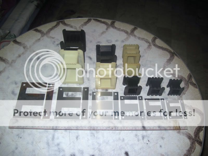
picture of cores and bobbins i use, these are scrapless types..from left to right 2inch to 1inch center leg.....
hmmm, is that a step up traffo? there are more secondary turns than primary ones...
Yes.. i remove it inside my old Automatic voltage regulator (AVR)
Can i wind the same primary windings?
Yes.. i remove it inside my old Automatic voltage regulator (AVR)
Can i wind the same primary windings?
hard to say since i did not see your avr.....if indeed you identified your primary and secondaries correctly, i don't see why not....
Tony,
Quick query about .. transformers.
On P.Turner's website, on his output-trans-PP-calc-3 page there is a diagram of a winding Figure 11.
He has a winding connected to the tube cathodes but it is not the middle winding .. it is sort of wrapped around the middle winding, there is a bit of overlapping going on ... is that right, also not physically connected .. connected inductively ?
Say he had a situation like this:
6 Secondary sections(one layer per section): S S S S S S
5 Primary sections(two layers per section) | | | | | | | | | |
| Ca Ca |
An An
I don't understand the overlapping, is there an electrical reason for that ?
For example would this be ok ?
S S S S S S
| | | | | | | | | |
| Ca Ca |
An An
Thanks
That was fooked up:
-S______S______S______S______S______S
___P_P_____P_P____P_P____P_P____P_P__
__An_____________Ca_Ca____________An
is that the way it would be connected ?
is this ok ? .. ie. does it really matter as long as two get to the anodes and two
get to the cathodes [0v rail]?
-S______S______S______S______S______S
__P__P____P__P____P_P___P__P___P__P__
_An_________Ca_________Ca________An
Thanks
-S______S______S______S______S______S
___P_P_____P_P____P_P____P_P____P_P__
__An_____________Ca_Ca____________An
is that the way it would be connected ?
is this ok ? .. ie. does it really matter as long as two get to the anodes and two
get to the cathodes [0v rail]?
-S______S______S______S______S______S
__P__P____P__P____P_P___P__P___P__P__
_An_________Ca_________Ca________An
Thanks
needless to say, whatever you do with it , you have to get your phasings correctly or else your opt will not work as intended...
i suggest you start with simple configurations first, like 4 primary sections and 3 or 5 secondary sections...
you will find this links useful:
http://www.diyaudio.com/forums/tubes-valves/109165-opt-design-assistante-el84.html
http://www.diyaudio.com/forums/tubes-valves/185229-who-makes-their-own-opt-around-here.html
http://www.diyaudio.com/forums/tube...ansformer-lamination-stacking-techniques.html
http://www.diyaudio.com/forums/tubes-valves/150034-output-transformer-silicon-steel-amorphous.html
http://www.diyaudio.com/forums/tubes-valves/129030-using-mains-transformer-output-transformer.html
http://www.diyaudio.com/forums/tube...r-push-pull-output-transformers-say-150w.html
http://www.diyaudio.com/forums/tubes-valves/196839-output-transformer-power-rating.html
i suggest you touch bases with BudP, he gave me information that i promised not to divulge to another....
Tony,
Quick query about .. transformers.
On P.Turner's website, on his output-trans-PP-calc-3 page there is a diagram of a winding Figure 11.
He has a winding connected to the tube cathodes but it is not the middle winding .. it is sort of wrapped around the middle winding, there is a bit of overlapping going on ... is that right, also not physically connected .. connected inductively ?
Say he had a situation like this:
6 Secondary sections(one layer per section): S S S S S S
5 Primary sections(two layers per section) | | | | | | | | | |
| Ca Ca |
An An
I don't understand the overlapping, is there an electrical reason for that ?
For example would this be ok ?
S S S S S S
| | | | | | | | | |
| Ca Ca |
An An
Thanks
not sure what you meant by overlapping, those cathode feedback windings seems to be in the right place, Patrick wanted his configuration symetrical wrt B+ lead, just make sure there is an interlayer insulation...
Tony,
yeah, actually I see that now.
one query :
say the winding is arranged as follows with six secs and five primary sections.
each primary section has two layers only, how would I connect cathode feedback in this arrangement if required ?
///////////////////////// sec
__________________ prim
___________________ prim
//////////////////////// sec
__________________ prim >>> cathode feedback here ?
___________________ prim
|
|//////////////////////// sec
|
|__________________ prim
___________________| B+ prim
|
|//////////////////////// sec
|___________________ prim
___________________ prim >>> cathode feedback here ?
//////////////////////// sec
__________________ prim
___________________ prim
etc..
would that be ok ?
[I am trying to program insulation thicknesses and need to know where feedback windings would be placed if they are required. Mostly ok if there at least four layers in a primary section but problem if there is only two layers in a primary section, some of Pat Turner's winding arrangements have only two layers in their primary sections. ]
Any suggestions ?
Thanks
- Home
- Amplifiers
- Power Supplies
- Tony's latest traffo DIY build