I've always assumed that actual core area was 98% of theoretical, and that 2% reduction doesn't really matter. (I included that 2% in my spreadsheet btw.)
Checking data of Waasner EI cores (and also Vacuumschmelze for c-cores) the 98% is too optimistic.
I see about 92-93% for Waasner EI cores, which is a reliable source.
^the width of the lamination is 6 inches in the drawing therefore the tounge width is 2 inches....
stacked to 4 inches and you get a core with 8 square inches, stacking factor of 95% gives you a core area of 7.6
as per RDH3 you can get a core VA of 1796.......
Waasner catalogue: EI150Nc (stacking height 9.1cm which is a bit less than 3.6 inches) gives 940 watts of secondary power using the best quality 0.35mm grain oriented silicon steel.
I don't see how you would get 1796 watts out of a very slightly bigger core.
Are you sure you saw a 50/60 Hz specification instead of 400 Hz?
I'd rather trust "modern" specifications a bit more than RDH3 data of maybe tens of years ago.
we don't really know the type of core he is using, therefore i tend to be deliberately conservative in my estimations......
the RDH is maybe 50 years old, but i trust the knowledge found in its pages....
the RDH is maybe 50 years old, but i trust the knowledge found in its pages....
we don't really know the type of core he is using, therefore i tend to be deliberately conservative in my estimations......
I'd say you are very very optimistic by expecting almost double the power from that core....🙁 , or was the 17 hundred odd watts a typo?
I don't see how you would get 1796 watts out of a very slightly bigger core.
the volt ampere figure of 1796 is at best estimate, it is rarely achieved in practice, you have your copper losses and the window area that limits wire size and therefore power rating, in my experience, it is the copper limiting the power.....
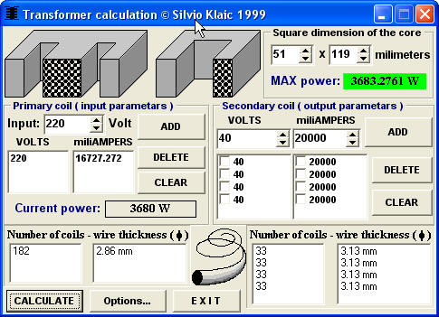
look at the picture below, it gives a core power rating even greater:
Last edited:
IMO that transformer calculator is not correct, the max power is much too high for that core. 220VAC with 16.7A primary (apart from winding space)? Forget it.
I just checked RDH3.
For core area in inch² the RDH3 formula is A = root of W / 5.58.
W = voltage/ampere (secondary power).
For a 940 watts core (the EI150Nc) with this RDH3 formula A should be 5.5 inch²; in fact the core is 6.5 inch², but this is for 1.6 T (Waasner specification). RDH3 formula is for 1.24 T.
Number of primary windings for 220V/50Hz is 224 with 1.24T according to RDH3.
Please note that RDH3 indicates 1.24T (80000 maxwell per inch²) for (at that time) good quality core material to be used for radio equipment!
That already indicates that core materials were lower grade at that time.
We discussed this already time ago: you can't use these pre-historic formulas for nowadays core materials. After all manufacturers supply the formulas which apply for todays materials, so use these.
what is missing here is power density follows flux squared. there's no way in hell you can get 3600 watts from a 51 by 119 mm core, at .9T!! At 1.4T, sure, in fact it would be about 95% efficient assuming the core loss is under 100 watts and you can stuff it 75% full of copper, which means #10 wire for the primary.
To get that power, you need an EI 231c, M6-0.35mm quality (this core weighs 23.2 kg, which is about two times the weight of the EI150 with 119mm stacking height):
According to Waasner (EI 231c):
- secondary power 3890 watts;
- induction 1.7 T;
- iron loss 69 watts;
- copper loss 58 watts;
- efficiency 97 %.
According to Waasner (EI 231c):
- secondary power 3890 watts;
- induction 1.7 T;
- iron loss 69 watts;
- copper loss 58 watts;
- efficiency 97 %.
what is missing here is power density follows flux squared. there's no way in hell you can get 3600 watts from a 51 by 119 mm core, at .9T!! At 1.4T, sure, in fact it would be about 95% efficient assuming the core loss is under 100 watts and you can stuff it 75% full of copper, which means #10 wire for the primary.
yes if you stuff all those coppers into a 1 inch x 3 inch window....primary and secondaries.....
i am using cores which i do not know the characteristics let alone the manufacturer they are 0.5mm thick....
Last edited:
i am using cores which i do not know the characteristics let alone the manufacturer they are 0.5mm thick....
Tony,
differencies between various qualities of iron are rather big.
When for example the M6-0.35mm EI150Nc core has 940 watts sec.power, 1.61T, iron loss 26.5 watts,
there is another quality 0.35mm with 760 watts, 1.37T, iron loss 32.9 watts;
one quality 0.5mm with 710 watts, 1.32T, iron loss 36.3 watts;
and one quality 0.5mm with 640 watts, 1.18T, iron loss 36.5 watts.
I guess the better quality of a particular thickness has had after treatment (heat), the worse quality not.
When interested I could scan some pages and send them to you.
Last edited by a moderator:
The core size is a basic determinant of transformer power (VA).
The core maximum flux is a secondary determinant. The absolute maximum range of VA for maximum flux of 0.9T to 1.8T is only 2times.
As an aside.
Does the Klaic software show a limiting ratio for stack width to stack thickness?
Could it be that the arithmetic is correct for a square stack and that beyond some ratio limit the error becomes too great?
What if Klaic had stated (or does he state somewhere?) a ratio range of 0.75 to 1.3 say?
50.8 to 119 is millimetres away from square, (I wanted to type miles but would get hammered for that exaggeration).
Does the Klaic software show a limiting ratio for stack width to stack thickness?
Could it be that the arithmetic is correct for a square stack and that beyond some ratio limit the error becomes too great?
That would make the software as good as useless.
For example, the EI96, EI120 and EI150N series start with stacking heights ("a" series) which make as good as square stacks; then we have a "b" series and a "c" series, the "c" series reach a ratio of almost 1:2 (EI150Nc has stacking height of 91mm).
Anyway I would not use that software; my Waasner data are reliable, being from the core manufacturer.
i know a good core when i see one......and knows what to do with it.....
my design goal in all my traffo builds is lowest operating temperature, i dislike traffos that you can fry an egg on top.........🙂
my design goal in all my traffo builds is lowest operating temperature, i dislike traffos that you can fry an egg on top.........🙂
The core size is a basic determinant of transformer power (VA).
The core maximum flux is a secondary determinant. The absolute maximum range of VA for maximum flux of 0.9T to 1.8T is only 2times.
As an aside.
Does the Klaic software show a limiting ratio for stack width to stack thickness?
Could it be that the arithmetic is correct for a square stack and that beyond some ratio limit the error becomes too great?
What if Klaic had stated (or does he state somewhere?) a ratio range of 0.75 to 1.3 say?
50.8 to 119 is millimetres away from square, (I wanted to type miles but would get hammered for that exaggeration).
no, power follows flux squared. double the flux, halve the turns, one fourth the resistance of the winding. you can now double the current and the voltage by doubling the flux. this is really quite simple. the power handling ability of a transfomer would produce a three dimentional graph against power, efficiency and tesla. Only this new 1.7, 1.8 and exotic 1.9Tesla iron hits a brick wall at those fluxes. older stuff that runs warm at 1.34T is the same iron that is used in your microwave oven transformer at 1.8 to 1.9T.
hi tony,
in video one, that guy winding secondary for first and the primary top of that.
is it correct?
^yes, as long as there is adequate insulation between primary and secondary winding's....
you can even arrange your windings as 2 x 40 => 1 x 230 => 2 x 40, in 3 sections......S1/P/S2...
with today's available dual bay bobbins, i casualy mix primary and secondary windings....
you can even arrange your windings as 2 x 40 => 1 x 230 => 2 x 40, in 3 sections......S1/P/S2...
with today's available dual bay bobbins, i casualy mix primary and secondary windings....
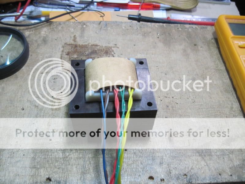
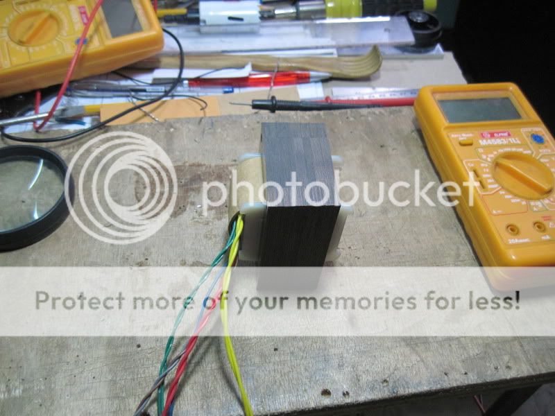
update:
this is a power traffo for a 6SN7 line preamp i am making, specs are:
230volt primary, about 60 voltamperes
310volts secondary @60mA
5volts @2amps
6,3volts @2amps
core material, RM-18, 0.35mm thick


dipping in polyurathane:
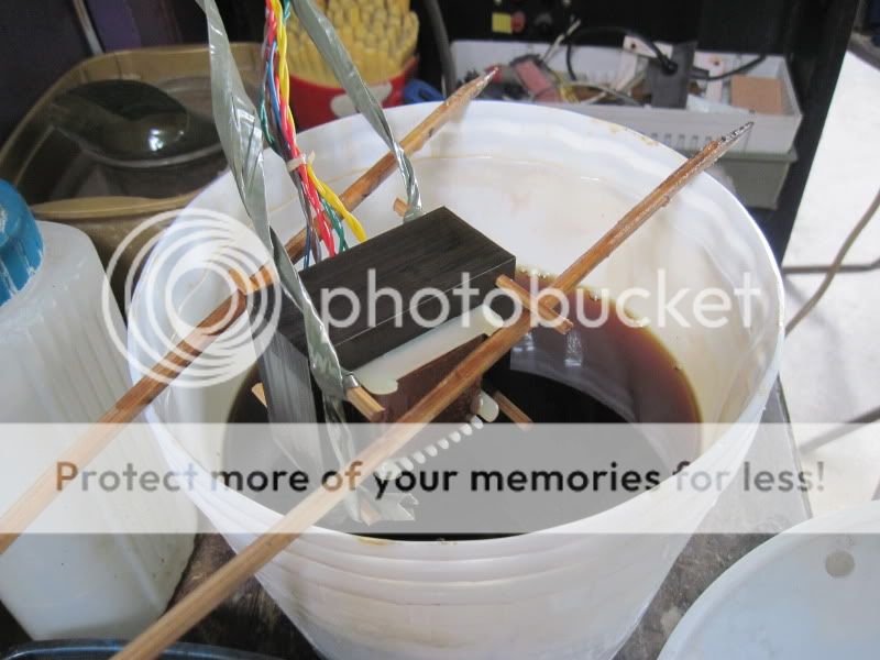
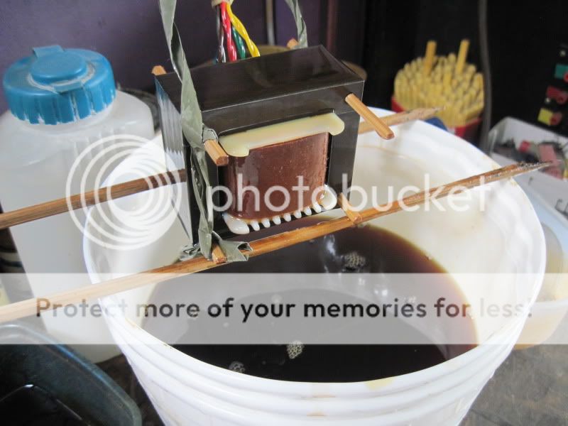
hanging out to dry fro 48 hours:

this is a power traffo for a 6SN7 line preamp i am making, specs are:
230volt primary, about 60 voltamperes
310volts secondary @60mA
5volts @2amps
6,3volts @2amps
core material, RM-18, 0.35mm thick
dipping in polyurathane:
hanging out to dry fro 48 hours:
- Home
- Amplifiers
- Power Supplies
- Tony's latest traffo DIY build