Vout at zero load current and Vout at rated load current give the transformer regulation.
Regulation = ((Voutzerocurrent/Vout@ratedloadcurrent)-1)*100
Transformer regulation is a measure of how much the voltage increases as the load goes to zero amperes.
If you have a bigger core area allowing a higher VA, then you have an increased rated current.
But if arriving at that increased current you have used the same window area requiring the same copper turns and the same copper area, then the copper resistance will have gone up due to the increased length of every turn. The increased resistance at the higher VA and higher current will give a higher sag in voltage (or a bigger difference between Voutzero current and Vout@rated current).
i.e. regulation has gone up.
but no one does this. when you increase the core area, you reduce the number of turns in order to keep the flux density at a constant level and increase the copper area of each conductor. the transformer becomes more efficient, lower losses, lower voltage drop under load.
if as you say, "you have used the same window area requiring the same copper turns and the same copper area, then the copper resistance will have gone up due to the increased length of every turn."
then what you've done by increasing the core size is reducing the flux density in the steel. this reduces no load losses, noise, stray fields, but everything else is worse.
if you hypothetically made a transoformer from 60 microwave oven cores in a line, it would be about 6 meters long, you would only need 2 turns for a 120v coil. it would have about 600 watts of parasitic load, would be rated for maybe 30kilowatts. (500 watts per core) and would weigh about 300 kilograms.
a 300 kilogram three phase transformer normally has about 250 watts of no load losses, and would be rated for 75 to 125 kilowatts. so you can quickly see that re-arranging the same steel into a more ideal shape (such as a 1:1 core cross section ratio) is far better.
Last edited:
then what you've done by increasing the core size is reducing the flux density in the steel. this reduces no load losses, noise, stray fields, but everything else is worse.
yes, and designing and building traffos is all about compromises,
we know what the ideal looks like, but there are a lot more important considerations too...
so knowing what is important to you, you can make traffos that are up to the task you sought out at the start...
knowing where you want to be and how to get there, that is the fun part...
yes, and designing and building traffos is all about compromises,
we know what the ideal looks like, but there are a lot more important considerations too...
so knowing what is important to you, you can make traffos that are up to the task you sought out at the start...
but his comment reads as if you can't reduce the number of turns and increase the diameter of the wire. as he posted a few posts back
when you keep the flux density the same, but double the core cross section of the transformer from 1:1 to 1:2, the copper path length was 4, now its 6. But you only need half as many turns, so it would be as if it was a copper path of 3 equivalent. but half as many turns means you can double the cross sectional area of the wire. so now the resistance is equivalent to a path length of 1.5. so if you had 4 ohms earlier, now you have a 1.5 ohm coil. if the capacity was 1 kilowatt before, now you can pull 1.63 kilowatts and achieve the same losses. but since the copper path increased 50%, you may be able safely increase the load until you get 50% more losses. which would be 2 kilowatts.As the ratio is stacked longer, the copper window remains the same but the iron limited VA is going up and the copper length is going up. These two effects increase the transformer regulation and lead to a big sag in voltage as the load current is increased.
It would be better to select a wider/bigger EI for improved transformer performance and probably end up lighter and cheaper and lower regulation due to less iron and less copper length for the new bigger VA.
it would be better to use the next larger core size, because you could get more power from the same mass of steel and copper, but it would run hotter because its surface area doesn't increase the same way. but doubling the length of a transformer doubles its VA and the efficiency Is higher than it would be if you simply ran two transformers in parallel. in this example, two of the 1:1 cross section coils would have a net copper resistance of 2, that is, a path length of 4 divided by two transformers. by doubling the length of the cross section, the copper resistance is 1.5 in this example.
Last edited:
but his comment reads as if you can't reduce the number of turns and increase the diameter of the wire. as he posted a few posts back
increased core area means lesser turns, lesser turns means you can use bigger diameter wires.....all within the constraints of the available winding window...
i try to use 80% of that window area for copper and of the 80 percent, 50-50% each for primary and secondary coils...
he is just theorizing, i doubt he actually makes his own traffos judging by the way he posts....
it would be better to use the next larger core size,
it is better to use the next bigger core size if you depart too much from a square cores section area...
but given materials already on hand, then you can make your traffos with what you have....in any core geometry you want...
ah, yes. sometimes i forget to look at the larger picture.
but i don't want other people confused. i hope my analogies are easy to understand.
but i don't want other people confused. i hope my analogies are easy to understand.
Agreed. Using near 1:1 uses the iron more effectively and uses the copper more effectively. The result is a lower regulation.but no one does this.................. you can quickly see that re-arranging the same steel into a more ideal shape (such as a 1:1 core cross section ratio) is far better.
You already know I don't try to make transformers. I have confirmed this many times and never try to hide that fact....................... i doubt he actually makes his own traffos judging by the way he posts..........................
if you hypothetically made a transformer from 60 microwave oven cores in a line, it would be about 6 meters long, you would only need 2 turns for a 120v coil. it would have about 600 watts of parasitic load, would be rated for maybe 30kilowatts. (500 watts per core) and would weigh about 300 kilograms.
a 300 kilogram three phase transformer normally has about 250 watts of no load losses, and would be rated for 75 to 125 kilowatts. so you can quickly see that re-arranging the same steel into a more ideal shape (such as a 1:1 core cross section ratio) is far better.
I understand what you're saying. But I'd suggest not to compare apples with oranges, as a three-phase transformer itselves provides a lot more utilization of copper and iron, compared to a single phase one.
Best regards!
But I'd suggest not to compare apples with oranges, as a three-phase transformer itselves provides a lot more utilization of copper and iron, compared to a single phase one.
yes......
3 phase transformers are worse than single phase when comparing efficiency, power density and impedance.
The example i gave is of commertial availability. 9:1 full load to no load power losses. They make them that way because its the most efficient for average 35% load over 24 hours.
Yes you really can get 120kw from a 300kg transformer. Maybe 25% more if it was single phase, at 99% eff and 5% impedance.
my respect to you gentlemen'
the theories and experiences you have make us realize the importance of every aspect in making traffos.
but like sir tony says when you already had the materials at hand you may use it but with corresponding consequences... my concern in making such traffo was due:
a. i need a 500va traffo
b. 1.5CL is the only available stock in the area thus any larger core size not available
c. there were no toroid available in the market only 200VA - 300VA and very expensive.
d. 500VA or higher toroid shall be ordered through net but very high costs i'm just a poor hobbyist.
my only choice was to make it a try on this. i have appreciated all the efforts in making a more comprehensive discussions...looking forward to your support later...
thank you...
best regards
sam
@johansen, just to remind all, this thread is for single phase small power traffos...
The fundamentals are the same. As the transformer increases in volume it's leakage inductance increases together with power density and efficiency.
Not sure what is meant by 1.5CL in the post just above yours?
EI-134 with hopefully a lot of taps 🙂
Hi, a marvellous thread making me confident to show my noobiness 🙂.
1: Well I have two Jefferson Magnetek 636-1211-000 that I have taken apart. I measure them to be EI-134's if this size exists. The iron + bolts and stuff are in two boxes for now. Do I need to clean them somehow as there are residues of old laquer on them? One is a bit oily too.
2: As I need to build bobbins for them I have bought epoxy resin plates 1.5mm for the central structure and for the intermediate "fences" dividing the windings and 2mm plates for the outer "fences". Is this the way to go dividing the windings along the central stack? Or should I just put one winding on the top of another? Besides the thickness of the intermediate fences is one approach more efficient than the other?
3: I have found the transformer calculation sheet, by Manfred Mornhinweg but it gives only one secondary - how should I think and calculate the winding area for many secondaries? Fx 600V 0.4A , 12,6V 3A, 6,3V 6A and 5V 2A. Could the low level secondaries be stacked and maybe taken taps out of the same winding?
4: Surely this has been written about many times and shown in pictures about how to take out a tap what would be the most usefull 6 HT taps from 300-600V? Is it as easy as saying it is 7 equally spread starting at 300? 50V spread...
5: When happy should I before inserting the last 10 laminates drop it into polyuretane with vacuum and after that put in the last ones and tighten it befre giving it another splasch in the can?
Of these number 2/3 are the ones where I'm struggling right now.
Some pics are allways welcome 🙂


Oh I forgot to say that the thickness of the laminates are below 0,4mm so I hope the Flux Denity could be safely raised to 1,1T.
But rather safe and sound I happily go for 1T...
Do I need to taper the wire between the different taps from 300 - 600V? Starting with a thicker thread and when convenient take a thinner one?
Enough - I need answers 😉
Regards
Hi, a marvellous thread making me confident to show my noobiness 🙂.
1: Well I have two Jefferson Magnetek 636-1211-000 that I have taken apart. I measure them to be EI-134's if this size exists. The iron + bolts and stuff are in two boxes for now. Do I need to clean them somehow as there are residues of old laquer on them? One is a bit oily too.
2: As I need to build bobbins for them I have bought epoxy resin plates 1.5mm for the central structure and for the intermediate "fences" dividing the windings and 2mm plates for the outer "fences". Is this the way to go dividing the windings along the central stack? Or should I just put one winding on the top of another? Besides the thickness of the intermediate fences is one approach more efficient than the other?
3: I have found the transformer calculation sheet, by Manfred Mornhinweg but it gives only one secondary - how should I think and calculate the winding area for many secondaries? Fx 600V 0.4A , 12,6V 3A, 6,3V 6A and 5V 2A. Could the low level secondaries be stacked and maybe taken taps out of the same winding?
4: Surely this has been written about many times and shown in pictures about how to take out a tap what would be the most usefull 6 HT taps from 300-600V? Is it as easy as saying it is 7 equally spread starting at 300? 50V spread...
5: When happy should I before inserting the last 10 laminates drop it into polyuretane with vacuum and after that put in the last ones and tighten it befre giving it another splasch in the can?
Of these number 2/3 are the ones where I'm struggling right now.
Some pics are allways welcome 🙂
Oh I forgot to say that the thickness of the laminates are below 0,4mm so I hope the Flux Denity could be safely raised to 1,1T.
But rather safe and sound I happily go for 1T...
Do I need to taper the wire between the different taps from 300 - 600V? Starting with a thicker thread and when convenient take a thinner one?
Enough - I need answers 😉
Regards
Last edited:
Of course another thougt has surfaced - should I have a central tap to ground and equally spread the voltages into two? Seems to be the way to go. Do I have to symmetrically use the corresponding voltage on the other side at any time or could I freely choose what windings to use at any time?
Regards
Regards
Hi Turbon,
1. 600V 0.4A , 12,6V 3A, 6,3V 6A and 5V 2A. this is very doable, and since
your application is a tube amp, the 1T seems reasonable since you are in a cold country.
2. measure your winding window, in your calculations, allot 80% for copper, and then 50-50 for primary and secondary windings.
3. i use a wire ampacity of 500 circular mils per ampere but it can vary more or less..
4. 1.5 mm thick bobbin seems a bit too much...but go with it for now and see if windings
fit the window..
5. once you have determined the primary turns, select a wire based on 500cm,
5.1 count the turns per layer,
5.2 count the number of layers,
5.3 count the primary build up using the wire diameter
seeing to it that it conforms to #2. if it does not then
select one size lower....
6. do the same for the secondaries....
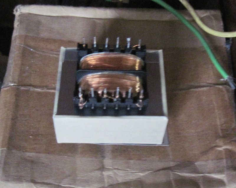
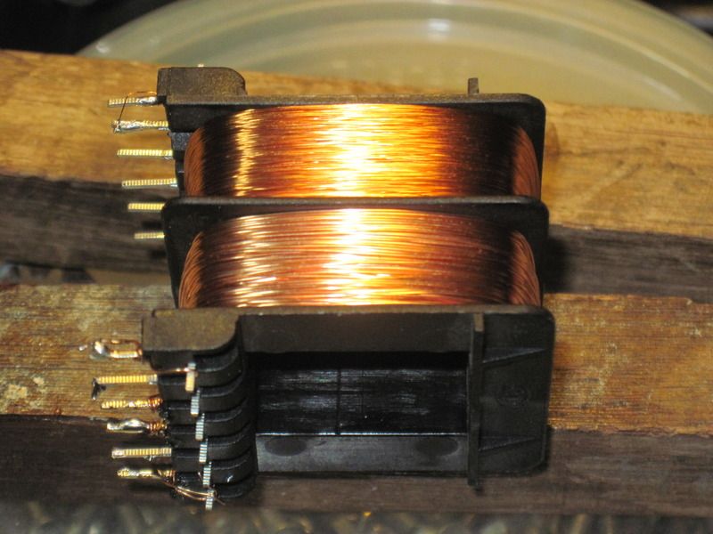
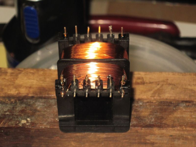
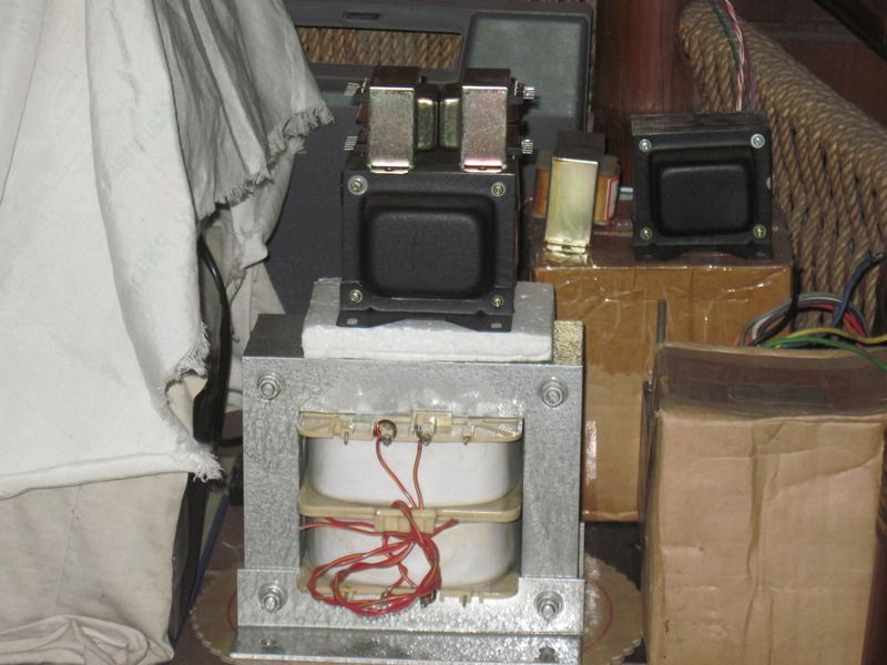
small traffo this time....5/8 inch x 20mm
2 x 12 volt secondaries to power soft start and speaker protection relays...
2 x 12 volt secondaries to power soft start and speaker protection relays...


- Home
- Amplifiers
- Power Supplies
- Tony's latest traffo DIY build