PP EL34 UL with Williamson-style driver, using 5687 as the PP driver stage.
Uses EL34 plate to 5687 cathode loop NFB.
Do you get subsonic peaking from the zero in the feedback 5uF/33K ?
Thanks, as always,
Chris
Do you get subsonic peaking from the zero in the feedback 5uF/33K ?
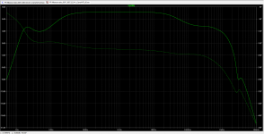
Yes, it's there. It's -5dB from 1kHz at 2Hz, though. Shown in the attached graph. I probed that at the grid of U3 (EL34). It looks pretty much the same at the grid of U4.
Does that look like it will be a problem?
--
Edit to add: I increased the value of C10 and C11 to 1000uF. That decreased the peak at 2Hz by about 6dB. I understand that the long time constant in the EL34 cathodes may cause blocking problems. But decreasing the value of C10 and C11 to 330uF increased the 2Hz peak by 6dB. Offsetting problems here.
Also: I put a 100pF cap in parallel with R19 (47k plate load resistor for U1). That tamed the broad peak from 700kHz to 1MHz or so. Closed loop -3dB point is at about 48kHz now.
--
Attachments
Last edited:
Yes, it's there. It's -5dB from 1kHz at 2Hz, though. Shown in the attached graph. I probed that at the grid of U3 (EL34). It looks pretty much the same at the grid of U4.
Does that look like it will be a problem?
Just on general principals, it's a good idea to have the equivalent of a "dominant pole" at low frequencies. Williamson recommended (in his later papers) setting this around 4 Hz and locating it at the output tubes' grids (because clipping occurs here in an optimized design, and we want to minimize hang time when clipped). Stability is a potential issue too.
All good fortune,
Chris
Edit to add: I increased the value of C10 and C11 to 1000uF. That decreased the peak at 2Hz by about 6dB. I understand that the long time constant in the EL34 cathodes may cause blocking problems. But decreasing the value of C10 and C11 to 330uF increased the 2Hz peak by 6dB. Offsetting problems here.
You might try making the cathode bypasses *very* large, but the 5uF/33K is causing the problem. I'd still want the cathode circuit time constant to be very far away from 4Hz, at least a decade lower. This is a major weakness in all the old classic designs.
All good fortune,
Chris
Of course, the 5uF/33k is also giving us lower rp and distortion from the EL34's, which should yield better damping factor and lower distortion. Once again, there ain't no free lunch.
What happens if I give the EL34's a single common cathode resistor and leave it unbypassed?
--
Answer: That totally cures the 2Hz resonance, but it also increases the distortion by 2X, and changes the distribution of harmonics so that 3HD is higher than 2HD. It's still low, though, at 0.039% at 1W into 4 ohms. But that's closed loop, which isn't all that great.
I'm not seeing any benefit from raising the cathode bypasses higher than 1000uF. I tried up to 4700uF, but it only decreased the 2Hz resonance a tiny bit. The difference between 330uF and 1000uF is large, though.
--
What happens if I give the EL34's a single common cathode resistor and leave it unbypassed?
--
Answer: That totally cures the 2Hz resonance, but it also increases the distortion by 2X, and changes the distribution of harmonics so that 3HD is higher than 2HD. It's still low, though, at 0.039% at 1W into 4 ohms. But that's closed loop, which isn't all that great.
You might try making the cathode bypasses *very* large, but the 5uF/33K is causing the problem.
I'm not seeing any benefit from raising the cathode bypasses higher than 1000uF. I tried up to 4700uF, but it only decreased the 2Hz resonance a tiny bit. The difference between 330uF and 1000uF is large, though.
--
Last edited:
Hmm, I only see an idle current stabilization feedback to the 1st screen grid there. Am I missing something, like some output Schade resistors?
Yes, you are not reading the text, just looking at schematics. 😛
I prefer 1-stage inner loop, because it sounds less nasty on overdrive by peaks than 2 stage inner loop ("Clinical" term means harsh overdrive, not low just distortions, actually) ;-)
240K go to anodes of 6P15P from anodes of GU-50 tubes; GNFB goes to cathode of the 1'St pentode.
Of course, the 5uF/33k is also giving us lower rp and distortion from the EL34's, which should yield better damping factor and lower distortion. Once again, there ain't no free lunch.
I sorry I wasn't more clear. The issue comes from the time constant; making it sufficiently larger than the grid couplings' time constant is what's needed. 50uF or 100uF should do it.
I'm not seeing any benefit from raising the cathode bypasses higher than 1000uF. I tried up to 4700uF, but it only decreased the 2Hz resonance a tiny bit. The difference between 330uF and 1000uF is large, though.
Cool beans!
Much thanks,
Chris
Williamson Mods
Hi , I have build a pair of these great amps back in -started in 89 and finished in 90 .. Stainless chassis with oak and panels . I used the individual tubes ... 4 6J5G's(better sounding than the metal ones) , 2 KT66 (from Groove tube years ago ) and 5v4/G for the rectifier . All original circuit but went 10 mfd on the filter caps . The other mod was a 3200 ohm primary 50 watt output transformer from Hammond-not a "Williamson" transformer . NO feed back is necessary, although I have tried it and left it off . Put a signal attenuation resistor and .1 tantalum cap on the input and the sound is super! Accurate clear sound .
I have played instruments and sang in past years . When you hear the harmonics of piano string/s and singers voices clear and accurate. its a winner for sure . I am using these to run the mid bass 'high end on a pair of old AR9's . The woofers are run by an SAE transistor amp .through electronic crossover . These circuits are all + - 20 % and parts today are much better I just used off the shelf parts ,nothing fancy.
I listen with my ear and not measurements , your ears will let you know its a good design no matter what(I used the 1949 schematic) ..also , don't forget the pre amp he designed .. the Heathkit WA-P2 is the design .. You can hear the clarity like few other designs . I have connected these to MAC tubes amps and you can easily hear a big difference. Pilot also used this design also using KT66 outputs and the 6BQ5's in their audio equipment. I have those also .. and they too are great sounding . Remember , its what sounds good to you that really matters . If you have the time to build these , I highly recommend,they have been good for me for a long time now-- almost 30 years.
- Status
- Not open for further replies.
- Home
- Amplifiers
- Tubes / Valves
- Today's Version of The Williamson Amp