No, stability-wise it is not equal! You can increase a local feedback up to a unity gain with no problems at all, except forcing the driver to work harder.
Sy, what power output do you think a single EL84 can get to in triode mode being driven by a source follower before grid 1 suffers?
Good question for which I have no data. Nearly every amp I've built with AB2 has used 6L6-types (7027, 6L6GC), and there I was able to get 50 watts out of triode push-pull without killing anything.
"Question re: local feedback between two PP stages -- In this sim, there is a loop from the plates of the EL34's to the cathodes of the preceding PP EL84's. I lifted that from one of the RCA Tube Manual amps. Is that a worse way of doing local NFB than plate-grid ("Schade feedback")? "
Putting the NFB loop back to the driver cathodes includes both stages of gain (driver and output) in the loop. Which could make stability a concern if they are high gain tubes. On the other hand, there is no OT in the loop, except as a load, so the phase behavior should be much better behaved. Much better than global Fdbk stability, which routinely handles several stages and the OT. The extra gain will reduce the output tube distortion considerably more than a simple plate to grid Schade loop. It may work so well as to summon the "clinical" sounding epithet, but that's just low distortion for you. It also keeps the input impedance high for the driver, good for the pre-amp.
I assume you were looking at the RCA 50 Watt schematic in their handbook. They used nested loops, a short inner Schade loop, and then a plate Fdbk back to the driver cathode loop, and finally a global loop. Each inner loop helps reduce phase problems for the next outer loop, by enhancing the enclosed performance. So that is a useful approach to insure stability of outer loops with high gain. It does however waste some gain, since inner loops are a less efficient usage of gain (as far as dist. reduction), and there is a finite amount of gain available (each inner Fdbk loop reduces the gain available to the outer loops). If OTs were perfect, then just a global loop would be the final answer.
RCA no doubt wanted a DIY schematic that was foolproof. No stability issues. Although the inner Schade loop really loads the driver plate and reduces gain. (a Mosfet follower in there could fix that)
With the high gm video driver tubes available now, it is a good approach. And if you can skip the inner-most Schade loop (and still keep stability) the cathode/driver Fdbk will offer mega linearization. But it's likely going to be "clinical" sounding. Ie, working really really well at reducing distortion.
Suggest putting an AC balance pot in the splitter to allow some mellow 2nd harmonic as an option (knob accessible).
Last edited:
That's really interesting. Since I've been able to make a PP 6L6-triode amp that sounded reasonably pleasant open loop (although it sounded better with a bit of gNFB), I figure I can simply add the 6L6-plate to driver-cathode feedback to taste. Too 'clinical' sounding? Raise the value of the plate-cathode resistor (reduce the level of negative feedback), à ton goût.
In the spice schematic I posted, I futzed with the plate-cathode FB resistor value until I got -6dB of feedback (0.5x gain).
I've made a few PP triode amps to which I've added global NFB, and while I enjoy the decreased distortion and tightened bass response, I don't enjoy the sort of 'hard but dull' sound that I think probably comes from OPT-induced phase problems. If I could lower distortion and increase damping factor without that problem, I'd be pretty happy.
So, to make sure I got this straight, a feedback resistor going from output tube plate to driver tube cathode is an OK idea for use with triodes? I'm going to try it in a non-virtual amp...
--
Has anybody tried Duerdoth's very simple (in principal) method of just changing the above-audio band response so that total loop roll-off in that region is effectively single-pole?
I think that is what Hafler in 1956 'Modernize your W' was after by introduced a 100pF capacitor from driver anode to global feedback cathode to achieve additional 12dB margin.
I think that is what Hafler in 1956 'Modernize your W' was after by introduced a 100pF capacitor from driver anode to global feedback cathode to achieve additional 12dB margin.
Schade and (even more so) the plate back to driver cathode loops will reduce the output Z of the final tubes. This makes the OT perform better since it overcomes distributed capacitance current at HF, and core magnetizing current at LF. Most OT problems can be solved on the primary side by these local loops. You are just left with leakage inductance at HF and winding resistance. Moderate global feedback can fix those (unless you want mega damping factor, not really that useful anyway).
The plate back to driver cathode loop performs the best for a local loop, as long as you don't overdo the enclosed gain obscenely ( a pentode driver with a gyrator load). The increased driver input Z is the most benign too, since previous tubes like high Z loads.
---------------------------------------------
One issue with these local loops fed back from the plate, is if the OT has high leakage inductance. The local loops make the plate linear V, and constant gain, with respect to the input signal. If the OT has high leakage L (often more on one side too), then the plate needs to expand its gain to overcome that at HF. So the global loop is left to perform that function (where it's not so good at HF). Somewhat of a waste, since a pentode output stage would normally expand its output (acting as a current source essentially) automatically.
So it can be advantageous to sample the "local" V feedbacks from a point more closely coupled to the actual output, like a UL tap, or a close coupled CFB winding (which would then automatically allow the plate to swing the required amount). But this then increases the effect of OT phase problems on stability of the inner loop(s) (feedback partially thru the OT), making for less usable loop gain before stability problems set in. So it becomes a matter of how well the OT is wound, limiting the liberties that can be taken.
The UL output stage and the CFB stage (and Schade from UL taps) are examples of this working well for an inner loop. So one might consider one of these as the inner-most loop.
-------------------------------------------------
Another good inner loop approach is to put current sampling sense resistors in the output tube cathodes. This will provide local feedback sources that make for a linear transconductance to the output, rather than linear V gain. And if done differentially, will make for final output current linear with input (removing crossover dist.) This inverts the OT problem however, now leakage L is handled well locally, but distributed winding capacitance is not. (un-accounted for HF current)
The very best solution is to combine both V and I feedbacks to obtain a controlled impedance at HF instead (rather than V or I alone). One can make that Zout (and load paralleled) match the critical damping of the leakage L and distributed C of the OT. So both leakage L and distr. C are brought under local loop control at HF. The global loop then only has to deal with winding resistance.
------------------------------------------------
Since the OT leakage L, distributed C, and winding R are relatively fixed constants (but different typically for each side of the OT), one can get really sneaky and just include proxy reactances in the local feedback paths of V or I pickup signals to compensate for them (essentially making a negative reactance source to cancel). And with an I pickup, one can put in a proxy resistance to compensate the winding resistance ( creating a resultant neg. resistance to cancel the OT winding resistance). Now all the global loop has to do is make sure you didn't over-compensate them. That's all up there in amplifiers 301 (the grad course).
Last edited:
Great stuff, smoking-amp. Thanks!
Up to this point, I'm with you. If I were to stop right there, I'd take a pre-existing push-pull amp that performs reasonably well open loop, and add an inner feedback loop from output tube plates to driver tube cathodes, listen to it and measure as best I can, then if necessary, add a touch of global NFB from the OPT secondary to the input tube cathode to (as Miles Prower says) 'take the edge off.'
It seems to me that the output plate-driver cathode feedback scheme is easier to implement than the 'Schade' output tube plate-grid loop. I'm going to look in RDH4 for a discussion of this that might help me understand the pitfalls. (There have to be pitfalls. I know they're there, somewhere.)
Beyond the above, well, I'm seriously out of my depth. Leakage L, winding C, winding DCR, all sound more difficult to compensate for. Correcting something as complex as an output transformer is beyond me. My hope was to lower the plate resistance of the output tubes in order to reduce the effects of the OPT on the output tubes. Beyond that, I'll just hope the leakage L and winding C of my OPT's aren't heinously awful.
Thanks for writing out your thoughts on this. I'll be reading it for the fourth time in a minute. 😉
--
Schade and (even more so) the plate back to driver cathode loops will reduce the output Z of the final tubes. This makes the OT perform better since it overcomes distributed capacitance current at HF, and core magnetizing current at LF. Most OT problems can be solved on the primary side by these local loops. You are just left with leakage inductance at HF and winding resistance. Moderate global feedback can fix those (unless you want mega damping factor, not really that useful anyway).
The plate back to driver cathode loop performs the best for a local loop, as long as you don't overdo the enclosed gain obscenely ( a pentode driver with a gyrator load). The increased driver input Z is the most benign too, since previous tubes like high Z loads.
Up to this point, I'm with you. If I were to stop right there, I'd take a pre-existing push-pull amp that performs reasonably well open loop, and add an inner feedback loop from output tube plates to driver tube cathodes, listen to it and measure as best I can, then if necessary, add a touch of global NFB from the OPT secondary to the input tube cathode to (as Miles Prower says) 'take the edge off.'
It seems to me that the output plate-driver cathode feedback scheme is easier to implement than the 'Schade' output tube plate-grid loop. I'm going to look in RDH4 for a discussion of this that might help me understand the pitfalls. (There have to be pitfalls. I know they're there, somewhere.)
Beyond the above, well, I'm seriously out of my depth. Leakage L, winding C, winding DCR, all sound more difficult to compensate for. Correcting something as complex as an output transformer is beyond me. My hope was to lower the plate resistance of the output tubes in order to reduce the effects of the OPT on the output tubes. Beyond that, I'll just hope the leakage L and winding C of my OPT's aren't heinously awful.
Thanks for writing out your thoughts on this. I'll be reading it for the fourth time in a minute. 😉
--
re: Trobbins
"Has anybody tried Duerdoth's very simple (in principal) method of just changing the above-audio band response so that total loop roll-off in that region is effectively single-pole?
I think that is what Hafler in 1956 'Modernize your W' was after by introduced a 100pF capacitor from driver anode to global feedback cathode to achieve additional 12dB margin."
-----
That sounds rather similar to what the SS people are calling Transitional Miller Compensation or TMC lately. Except that it does not go back all the way to the input stage. (Baxandall and Leach seem to have known about TMC in the 70s)
Page 182 of Cordells book has a diagram.
Can't find any accessible article for Duerdoth.
IEEE Xplore Abstract - Some considerations in the design of negative-feedback amplifiers
Duerdoth's feedback compensation method was also summarized (perhaps a bit easier to digest) in RDH4, p.374-378.
I'll have to read that part of RDH4 and see if I can make some headway.
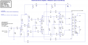
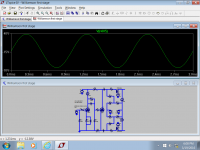
In the meantime, I used LTspice to do the math for me. I don't know if this would hold water in real life, but it looks good in the sim.
PP EL34 UL with Williamson-style driver, using 5687 as the PP driver stage.
Uses EL34 plate to 5687 cathode loop NFB.
Option to add gNFB from OPT secondary to cathode of input stage 6SN7.
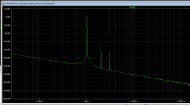
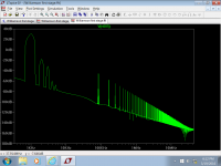
With no gNFB, just the local NFB from EL34 plate to 5687 cathode, it says 1W out into 4 ohms with 0.027%. THD. It looks like it makes 20 clean watts.
The gNFB appears to reduce gain and distortion by about 5dB. THD at 1W out becomes 0.016% THD.
2HD is a little higher in level than 3HD, in both the above cases. That should be a good thing, no?
I've included the .asc file for anyone who wants to play with it.
--
In the meantime, I used LTspice to do the math for me. I don't know if this would hold water in real life, but it looks good in the sim.
PP EL34 UL with Williamson-style driver, using 5687 as the PP driver stage.
Uses EL34 plate to 5687 cathode loop NFB.
Option to add gNFB from OPT secondary to cathode of input stage 6SN7.
With no gNFB, just the local NFB from EL34 plate to 5687 cathode, it says 1W out into 4 ohms with 0.027%. THD. It looks like it makes 20 clean watts.
The gNFB appears to reduce gain and distortion by about 5dB. THD at 1W out becomes 0.016% THD.
2HD is a little higher in level than 3HD, in both the above cases. That should be a good thing, no?
I've included the .asc file for anyone who wants to play with it.
--
Attachments
Thanks for the links to Duerdoth's publication and the RDH4 section. Whew, that is some heavy stuff, headache territory for sure.
Looks like peaking/phase shifting networks inserted in the amplifier chain to get the final gain/phase response to behave well. Might be some neat tricks in there, but one will have to read it 20 times to get a good feeling for how to design that. My first glance through it, gives me the feeling of doctors prescribing pills for symptoms, instead of causes.
From Trobbins comment:
"Hafler in 1956 'Modernize your W' was after by introduced a 100pF capacitor from driver anode to global feedback cathode to achieve additional 12dB margin"
I was seeing this along the lines of the recent Transistional Miller Compensation (TMC) idea the SS designers have been into lately, where they switch the source of Miller feedback, at some frequency, to a safer source (less phase shift).
But then translated to global feedback for the tube case.
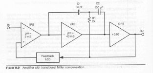
Below is a diagram of TMC from Bob Cordell's excellent book "Designing Audio Power Amplifiers" (SS) page 182. Hope that's OK, I highly recommend his book.
The TMC feedback in the diagram goes from OPS OUT through R1 and C1 at lower freq., and then from the VAS output through C2 and C1 at higher freq. Both going back to the VAS input.
So I was thinking of some kind of adaptation of that, where the global feedback would use the OT output up to the top of the audio band, then switch to plate output above that freq. range to avoid the OT phase issues. Seems that may have been what Hafler was up to also. Basically switching the global loop to a "local" (no OT) loop at a chosen freq.
Looks like peaking/phase shifting networks inserted in the amplifier chain to get the final gain/phase response to behave well. Might be some neat tricks in there, but one will have to read it 20 times to get a good feeling for how to design that. My first glance through it, gives me the feeling of doctors prescribing pills for symptoms, instead of causes.
From Trobbins comment:
"Hafler in 1956 'Modernize your W' was after by introduced a 100pF capacitor from driver anode to global feedback cathode to achieve additional 12dB margin"
I was seeing this along the lines of the recent Transistional Miller Compensation (TMC) idea the SS designers have been into lately, where they switch the source of Miller feedback, at some frequency, to a safer source (less phase shift).
But then translated to global feedback for the tube case.
Below is a diagram of TMC from Bob Cordell's excellent book "Designing Audio Power Amplifiers" (SS) page 182. Hope that's OK, I highly recommend his book.
The TMC feedback in the diagram goes from OPS OUT through R1 and C1 at lower freq., and then from the VAS output through C2 and C1 at higher freq. Both going back to the VAS input.
So I was thinking of some kind of adaptation of that, where the global feedback would use the OT output up to the top of the audio band, then switch to plate output above that freq. range to avoid the OT phase issues. Seems that may have been what Hafler was up to also. Basically switching the global loop to a "local" (no OT) loop at a chosen freq.
Attachments
Last edited:
Going back to the "local" N Fdbk schemes, and looking at Rongon's shematic, one would just put a small selected cap across (each) R13 and R25. This would cause the driver gains to increase in step with the leakage L loss in the OT at HF, to maintain constant output. (the two sides may require different size caps for typical OTs, and this assumes a nominal final load impedance) Obviously this can't be allowed to go on forever, so a ferrite bead or two would be put on the cap leads (each cap) to null out the cap effect at some freq. above the audio pass band (but below OT resonance). May have to be safely above the passband to avoid phase effects for the global loop.
The "local" loop was already controlling for magnetizing current and distributed winding capacitance current and output tube distortion. Now it is correcting for leakage L also (although this is open loop correction assuming a nominal load). We are only making corrections for the simplified OT model below OT resonance. Above resonance, things get too complicated.
Only thing left is OT winding resistance. If we put some current sense (low Ohm) resistors in the output tube cathodes, and source another (positive) feedback from them to the driver cathodes (high value resistor feedback paths from the sense resistors), we can cause the driver output voltage to increase with load current. Properly selected, it could null out the winding resistance loss to give constant output at the secondary. So now we are correcting the OT resistance, and producing a high damping factor for the speaker at the secondary, all from the primary side in a "local" loop. Not bad for local Fdbks.
The global Fdbk loop can just loaf along, with safe levels of global Fdbk through the OT to clean up any distortion residuals and loading effects (variation from nominal Zload). It could use the "Transitional Global Fdbk" idea above to put some high feedback in the loop. PPM amplifier anyone?
PS:
It might be possible to move the leakage L compensations over to the current (positive) feedback pathes to take into account variable load current, becoming closed loop corrections then. Probably have to use small inductors in series with the I feedback resistors (instead of the small caps across the driver cathode resistors). Then tiny caps across those series inductors to null them out at the top of the band.
Last edited:
As an interesting aside on the "local" loop compensations approach mentioned above, these are essentially "exact" Duerdoth phase correction networks.
These amount to what is called "unilateralization", where external compensated feedbacks remove the reactive components of internal device effects (defects). They use the internal model of the device to put in exactly opposite effects. If the internal model is correct, they have the effect of removing the annoying phase shifts at the output. So an OT correctly compensated with the "local" fixes would not even have the annoying two pole response that messes up global feedback. TGF (Transitional Global Feedback) would not even be needed. Just plain global Fdbk.
Of course our OT model is only really useful up to the first OT resonance, things getting complicated above that freq. with internal substructure (winding layout) causing further HF resonances. But the OT resonance is above the audio passband, so we are in good shape where it counts.
So TGF would still be useful for a really high global Fdbk (high gain front end) amplifier where gain-bandwidth used by the global loop does not drop to unity below the OT resonance.
Also, for various loop stabilities, one does not want to quite approach total-exact compensation due to OT model accuracy and OT model stability limitations (like thermal, aging, loading drift). (Too much correction and you have negative reactances left over, and likely a good oscillator.) So the global loop will be left with some unfinished work to do. As a practical matter, the DIY tweaker may have some compensation pots to adjust, and the distortion, freq. flatness, and damping factor will improve noticeably as you near the oscillation thresholds.
Last edited:
I prefer 1-stage inner loop, because it sounds less nasty on overdrive by peaks than 2 stage inner loop ("Clinical" term means harsh overdrive, not low just distortions, actually) ;-)
240K go to anodes of 6P15P from anodes of GU-50 tubes; GNFB goes to cathode of the 1'St pentode.
240K go to anodes of 6P15P from anodes of GU-50 tubes; GNFB goes to cathode of the 1'St pentode.
Attachments
Hmm, I only see an idle current stabilization feedback to the 1st screen grid there. Am I missing something, like some output Schade resistors?
-------------------
Clearly, the more O L gain put into an amp, the more careful one will have to be to keep clipping/overload problems under control. Lots of anti-saturation diodes.
-------------------
For the most complicated amplifier EVER, with Duerdoth compensation, multiple feedback loops .... take a look at this!! :
http://jrossmacdonald.com/jrm/wp-content/uploads/026MultiloopAmplifier.pdf
Here is D. Hafler's "Modernise Your Williamson" too:
http://www.tubebooks.org/file_downloads/modernize_your_williamson.pdf
Looks like TGF to me.
--
-------------------
Clearly, the more O L gain put into an amp, the more careful one will have to be to keep clipping/overload problems under control. Lots of anti-saturation diodes.
-------------------
For the most complicated amplifier EVER, with Duerdoth compensation, multiple feedback loops .... take a look at this!! :
http://jrossmacdonald.com/jrm/wp-content/uploads/026MultiloopAmplifier.pdf
Here is D. Hafler's "Modernise Your Williamson" too:
http://www.tubebooks.org/file_downloads/modernize_your_williamson.pdf
Looks like TGF to me.
--
Last edited:
J. R.s Active-Error Fdbk and Augmented Cathode Followers are definitely interesting reads. Haven't looked at everything....
One interesting question comes to mind about correcting the OT for global Fdbk. Two pole roll-off is what trashes global Fdbk. And Duerdoth comp. seeks to revert that to single pole roll-off.
Now the simplest "local" Fdbk scheme, like Schade or plate back to driver cathode, removes the distributed capacitance current effect, basically using near zero impedance drive (so shorting it out). Seems like that would revert the OT to single pole roll-off right there.
Just wondering if one really needs to do the full L and C correction if one is going to just use the OT itself to do the single pole roll-off for the global Fdbk. Looking at how to make the simplest amplifier.
Last edited:
Now the simplest "local" Fdbk scheme, like Schade or plate back to driver cathode, removes the distributed capacitance current effect, basically using near zero impedance drive (so shorting it out). Seems like that would revert the OT to single pole roll-off right there.
Just wondering if one really needs to do the full L and C correction if one is going to just use the OT itself to do the single pole roll-off for the global Fdbk. Looking at how to make the simplest amplifier.
I agree that simple is better. I've been playing around with ideas generated from SY's Impasse preamp. It works well with what I've been thinking about. How to make the amp simpler with just 1 voltage gain stage. Here's something I simmed that hasn't been built:
After much fussing I was able to get the linearity of the output pretty good right up to the 2V rms output of a standard signal source. It shows on the FFT at that level. I wasn't able to get the maximum theoretical mu of the voltage gain stage (20)even with an active load. An mu of 18 was all I was able to get. I just used a generic constant current symbol in LTspice. Maybe I was doing something wrong.
The point is that the output that would be going to the grids of the output tubes is pretty pristine. That isn't an aberration where the harmonics disappear obove the 5th harmonic. With lower input signal levels even the 4th and 5th harmonics disappear. I'm not sure what those harmonics are at 100khz and above but I'm pretty sure they either don't exist or could be handled easily.
The point is that it simulates an output of a very clean 99 volts peak to peak for a standard 2v rms input signal. It seems to me that's a signal level one could do a lot with standard tubes. For example a 6l6 in ab mode is biased at -37 volts, EL34 is 39 volts. You definitely don't have a lot of extra for feedback. But if you could get the MU of the gain up to the theoretic limit of 20 then you'd have a voltage P-P on the output of 113 volts. You could definitely work with that. Why put in an extra stage only to have to futz with it? Also, (not a minor point), The less stages of amplification the less distortion generated which you then have to try to reduce.
Attachments
It's a pretty small schematic I posted so I'll reiterate some details. It doesn't hue completely to SY's preamp. It uses 450 volts (the max for a 6sn7) not 350 volts. I also used 6SN7 for both gain and split load. You need the 450 volts for good linearity at maximum output. I used SY's idea of capacitively coupling between stages because it allows more optimization ability. I also noticed that the linearity got better as I biased the voltage gain stage to around 7 volts. I didn't expect that and I'm not sure why that is, but there it is. It allows for greater headroom on signal input peaks but you take a hit on power dissipation. You might have to go to a 6SN7 GTA or GTB to have a margin of safety in power dissipation.
Last edited:
- Status
- Not open for further replies.
- Home
- Amplifiers
- Tubes / Valves
- Today's Version of The Williamson Amp