That's a good tube to use there. A MOSFET will give somewhat lower distortion, though.
Hi !
But what where DC coupled Mosfet`s drive output power tubes cathodes instead of G1 grid`s ? , like true OPS Grounded Grid PP operation ?
Best Regards !
The "if properly applied" is quite a big if, though. There are a lot of pitfalls especially in valve amps. If you don't believe me, just try driving a Williamson into clipping. 🙂
Tried that with mine. It just flat tops.
What happens to yours?
Hi !
But what where DC coupled Mosfet`s drive output power tubes cathodes instead of G1 grid`s ? , like true OPS Grounded Grid PP operation ?
Could be done in an interesting way with p-channel devices.
Could be done in an interesting way with p-channel devices.
Of course !
Basically with Mosfet`s drain(s) connected to out.pow.tubes cathode(s) , source(s) connected on the ground line and with gate(s) driven with PP AF signals .
There is so many positive aspects from this hybrid G.G. approach .......
The only reason choke-input supplies were ever used in the first place was because cheap, small, high-capacity electrolytics didn't exist.
The key word there is "cheap". Again, that is the sole reason cap input supplies came to dominate. From a technical standpoint they are horrible. Crappy power factor, poor transformer utilization, worse regulation, much more harmonics and noise.......
They are about as relevant to hi-fi as vacuum tubes themselves. 😉
If you don't think tubes are hi-fi, then why get involved in a discussion in a tube amp forum 😕
Here's a quote from someone whom you might classify as an "idiot."
From "Valve Amplifiers," 4th edition.
Exactly the point made by Bruno Putzeys in the 'The F-word....' article. When, in his flight of fancy he modified a tube amp to have 60dB of NFB at 20kHz, people who listened to it were astounded that a tube amp could sound so good.
Jan
Sy, this is the article that I found a few weeks ago.
Yes, I've seen that. I think we can do better. 😀
Indeed. The article contains inaccuracies such as "The mains hum and the 3rd harmonic distortion component are in phase in the valves and consequently cancelled in the output transformer." Ehh, 3rd harmonic? No. And mains hum (dont forget noise from the crappy cap input filter) is never perfectly cancelled at the quiescent operating point. Furthermore, it becomes worse as the tubes operate over a cycle, with their respective gm constantly changing. PSRR is at it's worst when one side of an AB pair cuts off. Fortunately a good power supply solves these problems. Unfortunately, the author of that article recommends the worst possible power supply configuration.
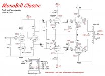
A recent Williamson amp using the Russian 6N6.
I have found you may need to change the value of the cathode resistor on the Voltage amp to get the Phase splitter correct.
Phil
Please specify which is the value of R18 or the correct bias for this schematic.
Thx,
M
Has anyone come across a scan of '"Williamson" type amplifier using 6A5's', by J.H.Beaumont, Audio Engineering, October 1950.
That issue is not on AUDIO - Consumer audio and music magazine from late 40's to 2000.
Ciao, Tim
That issue is not on AUDIO - Consumer audio and music magazine from late 40's to 2000.
Ciao, Tim
marl0w3
Please specify which is the value of R18 or the correct bias for this schematic.
Thx,
M
Hi M
I found about 600 ohms with the 6n6 i have, but depends on the tube you could fit a 1k pot.
i have found with just about any tube 12BH7 and more, an adjustable pot is best if you want the phase splitter to work correctly.
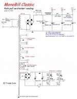
sorry: When i scanned the circuit for this amp i put the wrong power supply.
Phil
Please specify which is the value of R18 or the correct bias for this schematic.
Thx,
M
Hi M
I found about 600 ohms with the 6n6 i have, but depends on the tube you could fit a 1k pot.
i have found with just about any tube 12BH7 and more, an adjustable pot is best if you want the phase splitter to work correctly.
sorry: When i scanned the circuit for this amp i put the wrong power supply.
Phil
Attachments
ANYbody ever build the "Mono Bill" classic? Is there a wesite for the amp? It looks like an old Heathkit schematic. Consider using Edcor or Hammond transformers that are easy to obtain.This is a great project...or at least could be if the pro's help out....
power supply improvements
I did like the amplifier part described by Byrith and was contemplating building one...
What would be a good approach to a 'best possible' power supply for an amplifier like that. When I want good PSRR that typically involves active components - dare I say semiconductors. What do you suggest to keep with the spirit of the valve amp?
Something else that probably needs improving is that the HV kicks in before the valves have time to heat up. Other than using valve rectifiers (with the associated problems), are delay circuits used or is that again against the grain of things? Guitar amps just use a standby switch but that is not common in audio amps...
Indeed. The article contains inaccuracies such as "The mains hum and the 3rd harmonic distortion component are in phase in the valves and consequently cancelled in the output transformer." Ehh, 3rd harmonic? No. And mains hum (dont forget noise from the crappy cap input filter) is never perfectly cancelled at the quiescent operating point. Furthermore, it becomes worse as the tubes operate over a cycle, with their respective gm constantly changing. PSRR is at it's worst when one side of an AB pair cuts off. Fortunately a good power supply solves these problems. Unfortunately, the author of that article recommends the worst possible power supply configuration.
I did like the amplifier part described by Byrith and was contemplating building one...
What would be a good approach to a 'best possible' power supply for an amplifier like that. When I want good PSRR that typically involves active components - dare I say semiconductors. What do you suggest to keep with the spirit of the valve amp?
Something else that probably needs improving is that the HV kicks in before the valves have time to heat up. Other than using valve rectifiers (with the associated problems), are delay circuits used or is that again against the grain of things? Guitar amps just use a standby switch but that is not common in audio amps...
I have volume 2.
Do you guys want me to post a scan of the schematic?
Do you guys want me to post a scan of the schematic?
No scans, but it appears in vol 2 of Audio Anthology.
- Status
- Not open for further replies.
- Home
- Amplifiers
- Tubes / Valves
- Today's Version of The Williamson Amp