Yeah, I replace volume pots every decade or so. Connectors at below 50 V and below 20 ma are always suspect if not gold plated. This includes switching connectors like 1/4 or 1/8 phone sockets. volume pots have connections in them, the wiper. Read relay catalogs about dry circuit contacts. Those pins labeled "J4xx" in the pictures are interboard connects. They are highly suspect unless soldered or the pin and socket are gold (unlikely at this price point). Scrape the sockets out with a pick and the pins off with a screwdriver. Oxidized tin or brass is an insulator.
I don't replace transistors without a symptom like the DC being off. I might find a noisy one some day, but not yet. Japanese organs like old Yamahas are known for having the little white plastic transistors with the PVC cap described earlier - get rid of those. Fortunately I haven't bought any device with those transistors.
I've found really old circuits (60's and 70's) are sensitive to gain; too much gain leads to saturation and no sound flowing through. What gain was popular has a lot with what decade something was made.
Last edited:
Those pins labeled "J4xx" in the pictures are interboard connects. They are highly suspect unless soldered or the pin and socket are gold (unlikely at this price point). Scrape the sockets out with a pick and the pins off with a screwdriver. Oxidized tin or brass is an insulator.
I was wondering about that as well. Most wires are wrapped on the pins with no solder. I could just unwrap every wire off the connects. Should I add some solder on all of them? If there weren't so many wires I'd try and replace them with copper, but that would be crazy. I might do that only for the wires between the power amp board and the transistors on the heatsink.
Oxidized tin or brass is an insulator.
Worse. It's a rectifier. Not a good one, but you can use it to "detect" RF. That means distortion for audio signals.
Where it doesn't affect your ability to get into and out of the amp, I'd solder the tin plate interboard connectors. That has been done on several wirewrap boards of my hammond H100 organ. Wirewrap has proved good with gold pins, silver wire, and 1.4 v TTL logic signals. On the hammonds for low energy audio signals , it has proved a problem on 25 mv tone generator signals with tin plated wire and posts. There is a service bulletin about soldering the low voltage ones. The 24 v and 100 v power supplies running through wirewrap pins on my organ are not a problem.
Where it does affect your ability to get into the amp, I'd blow off the wirewrap part and just solder a half turn on the pin, so you can install it and remove it multiple times without damage.
Where it does affect your ability to get into the amp, I'd blow off the wirewrap part and just solder a half turn on the pin, so you can install it and remove it multiple times without damage.
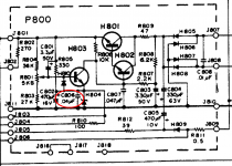
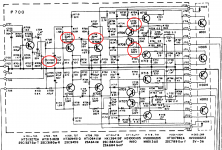
I started working on the power amp board and noticed something I haven't seen before.
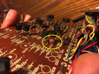
There's this diode, M8523 A-O noted in the service manual, it's thermal coupled to 2SC1384 transistor, and when I tested it, it conducts both ways. But it's not shorted, there's a voltage drop of about 0.250V each way and varies if I hold it between my fingers. There are actually two of these diodes on one board, both behave the same and conduct both ways. Is this normal?
There's this diode, M8523 A-O noted in the service manual, it's thermal coupled to 2SC1384 transistor, and when I tested it, it conducts both ways. But it's not shorted, there's a voltage drop of about 0.250V each way and varies if I hold it between my fingers. There are actually two of these diodes on one board, both behave the same and conduct both ways. Is this normal?
Attachments
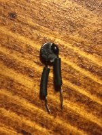
If both are alike I would leave it. thermal sensing of the output transistor stage is a good design feature; semiconductors usually have a negative temperature coefficient. But .25 v drop sounds like a germanium part, very obsolete. Don't lose or damage; these there won't be any more I'm sure.
More common is negative temperature coeficient resistance material, but again, getting a replacement with the exact resistance and temperature coefficient your board had originally is very unlikely.
Usually NTC parts are electrically in the stack between the upper driver and the lower driver transistor.
Its a thermistor not a diode. Refit them exactly as they were with regard to any thermal coupling. There purpose is to track and compensate the bias current as the amp warms. Without those you would get destructive thermal runaway.
Of course I'm going to install it the same way. Should I add some thermal paste between the diode and transistor? I'll put some heatshrink on them
Yes, some thermal coupler paste is good. General caution, the berylium kind of paste is poisonous, wash your hands afterwards.
I've been looking for some thermal conductive glue since my wires tend to pull the thermistor away from the transistor in my homebuilt packages, but until I do I've been using duco cement.
I've been looking for some thermal conductive glue since my wires tend to pull the thermistor away from the transistor in my homebuilt packages, but until I do I've been using duco cement.
Cool, arctic silver aata-5g says it is a thermal bonding adhesive. Newark (farnell) stocks it but I had never heard of it before. I had a blown temp sense "stabistor" (dual silicon diodes in a tiny package) in my 1.3 kw amp, and it was glued in somehow, I just didn't know how to buy the stuff. Thanks for the name. It's a non-stock supplier direct ship though, that makes an $8 tube a $16 purchase if they use UPS and $22 if they use Fed-Ex ground.
Newark says they also have a thermal joint compound from them, which I suppose is non-adhesive.
I've been using WEP brand thermal grease from 30 years ago, a company probably bankrupt or merged out of existance by now.
Newark says they also have a thermal joint compound from them, which I suppose is non-adhesive.
I've been using WEP brand thermal grease from 30 years ago, a company probably bankrupt or merged out of existance by now.
Last edited:
Yes, I've been using their products for my computers. I usually clean all my gear once every 6 months, clear the dust from heatsinks/fans and also reapply thermal paste to all processors.
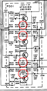
I measured the larger TO-92L transistors, and while the 2SA ones seem ok, one of the 2SC1384 ones measured just 80 gain. Datasheet specs it at 85-170. The other one was at about 100. 2SA684 were both at around 130.
I found these transistors on ebay but most likely fakes. Should I try and replace them? Or the position in the circuit makes it ok at 80 gain? They are specced as the lowest gain from the 3 options.
I found these transistors on ebay but most likely fakes. Should I try and replace them? Or the position in the circuit makes it ok at 80 gain? They are specced as the lowest gain from the 3 options.
"... measured just 80 gain. Datasheet specs it at 85-170...."
Most likely absolutely nothing wrong with it! Hfe varies with test current / voltage, and your little test meter will not duplicate the conditions specified (or implied) in the data sheet.
I admire you bravery in the wholesale swapping of components! Apart from aging elkos, a complete waste of time IME. But that is just me!
JB Weld does a fine job and conducts heat quite well for a hell of a lot cheaper than the AS stuff.
European 'BC' series transistors are inconvenient to use in most Japanese gear because of the pinout. Other than that, a list of the reasons not to use them is a short one.
European 'BC' series transistors are inconvenient to use in most Japanese gear because of the pinout. Other than that, a list of the reasons not to use them is a short one.
Be careful with both the thermistor and the thermal compound. Those thermistors are fragile, and once you break it you can't measure it to get a replacement. You might not even be able to get the same one. And some versions of Arctic Silver are electrically conductive. In some cases you don't want that.
Cool, arctic silver aata-5g says it is a thermal bonding adhesive. Newark (farnell) stocks it but I had never heard of it before.
...
It's a non-stock supplier direct ship though, that makes an $8 tube a $16 purchase if they use UPS and $22 if they use Fed-Ex ground.
You can buy it easily on Amazon. Check out the marketplace sellers.
Arctic Alumina Thermal Adhesive (AATA as you mentioned) is the one to get as it is totally non capacitive or conductive.
"... measured just 80 gain. Datasheet specs it at 85-170...."
Most likely absolutely nothing wrong with it! Hfe varies with test current / voltage, and your little test meter will not duplicate the conditions specified (or implied) in the data sheet.
I admire you bravery in the wholesale swapping of components! Apart from aging elkos, a complete waste of time IME. But that is just me!
I started with electrolytic caps, but then I saw how hard it is to service, so I thought I replace all resistors as well. Carbon resistors for that age can fail/drift. I actually found a few that drifted for 20% from the original value. I also did check the color code to make sure.
The boards were full of leaked electrolyte on top side and full of flux on the backside. Cleaning them was much easier with no parts installed. Desoldering station made that really easy.
All film caps measured fine, in spec. Ceramic ones as well. Since I did most parts I decided to check and maybe replace the transistors as well. This amp is a keeper and I want to have it top notch. Plus, as I mentioned, I do like this kind of work, it is therapeutic for me. Helps me focus on something for longer times. It's not about wanting audio nirvana, as liking this kind of work, searching parts, cleaning the guts of the amp. Seeing it rise again from my hands 🙂
If I would decide to replace the small ceramics, can I use similar values? Like 27/33pF instead of 30pF, 47pF instead of 50, and 220pF instead of 200pF, or 330 instead of 300pF? I'd put some new C0G types.
I noted them on the schematic. If someone who understands their role/implication can tell me if it would be ok or not I'd appreciate that. It's pretty hard to find the exact values.
On the Tone board (PE01 not PF01) there's 4 small ceramics that are near some transistors, those don't appear in the schematic at all. Nor in the parts list. They are 20pF, I could find 18/22pF I think.
I'd like to mention one more time, I am not looking to improve the sound, at all! I mean yeah, it would be nice if it did (it was sounding real nice to begin with). But I am more into the action of restoring the unit, rather than pursue audio bliss from that. I feel warm and fuzzy inside if I know I replaced most parts, especially ones that could have drifted/failed or be in general out of spec. 🙂 Something like an old beast with a new heart.
I don't want to install exotic parts in it and pretend it is something else than it is.
Attachments
Last edited:
Carbon resistors for that age can fail/drift. I actually found a few that drifted for 20% from the original value.
I'm very very surprised at that tbh. Are you checking them out of circuit and with clean probe tips/clean resistor leads. Also, you can't hold a high value resistor in your fingers and measure it because you also add your variable finger resistance in parallel to it.
- Status
- Not open for further replies.
- Home
- Amplifiers
- Solid State
- to92 transistor replacement