Wouldn't the space charge attract the positive ions, thereby bombarding the cathode? Or does the space charge provide a minute barrier, not letting the positive ions actually reach the cathodes? Just a theoretical interest here, and it's based on my image of positive ions and their inertia blasting through the electron cloud and hitting the cathode. Nothing empirical in my question.
The space charge around the cathode does both: it attracts positive ions, and provides the extra electrons to discharge that positive ion. That keeps most of them off the cathode, even in oxide cathode, gas or Hg vapour, types (diodes, thyratrons).
So I have one more related question. Taking a nod from the Bottlehead Quickie, what if we kept B+ ALWAYS powered on, but used the filaments to switch on the amp? With no cathode emission, seems like there'd be no conductance and therefore no current flowing in the tube - the amp would be, to all purposes, off. Turn on the cathode and the amp is on. This would mean no sudden surge of B+, though it would be present the moment the filament started burning, so the ionization would presumably occur as before). This would, of course, not work with a direct coupled amp (need that cap coupling to keep the DC sitting idly at the anode), and maybe would be moot given the placement of the OPT?
I'm just sayin'
This would be a fine idea if the inside was completely filled with vacuum. It isn't. Not even close. Leaving the HV DC on simply makes a cold cathode glow tube. Even if you don't actually see any glow doesn't mean that you're not ionizing the residual gas and slowly poisoning unprotected cathodes with ions.
One design I did used separate heater/HV switches. This design choice had nothing to do with any cathode stripping problems (the DC rail voltage wasn't high enough for that) but because the DC rail was a SS design, and the circuit itself used DC coupling. Preheating the cathodes before applying the HV means grids won't get overvolted since the DC rail comes up within a couple of seconds, even before cathodes can warm up. With the cathodes hot, it's just like switching on a SS amp.
Another design that used a 5U4GB for the main DC rail has just the one power switch. The 5U4GB warms up slowly enough so it's not a problem.
If the cathode is cold then there are no free electrons to ionise the gas, so you won't get continual poisoning.This would be a fine idea if the inside was completely filled with vacuum. It isn't. Not even close. Leaving the HV DC on simply makes a cold cathode glow tube. Even if you don't actually see any glow doesn't mean that you're not ionizing the residual gas and slowly poisoning unprotected cathodes with ions.
Wouldn't the space charge attract the positive ions, thereby bombarding the cathode? Or does the space charge provide a minute barrier, not letting the positive ions actually reach the cathodes? Just a theoretical interest here, and it's based on my image of positive ions and their inertia blasting through the electron cloud and hitting the cathode. Nothing empirical in my question.
The ions are attracted to the negative potential of the cathode, regardless of the presence or absence of a space charge. The space charge electrons will neutralize the ion, which prevents further acceleration. When there is current flow the electrons streaming towards the plate will put the brakes on the now neutral atom.
That is a simplified explanation BTW. In reality, the neutral atom can get smacked by another electron and become ionized again, and then neutralized, repeatedly. The point is that the space charge prevents the ion from striking the cathode at high velocity (or at all in many cases).
If the cathode is cold then there are no free electrons to ionise the gas, so you won't get continual poisoning.
A room temperature oxide cathode still emits the occasional electron. If you had a sensitive enough ammeter (measuring nanoamps) and did the measurements in a faraday cage (to shield out noise), you can readily measure current flow in a cold tube at normal operating voltages. Its minute to be sure, but it exists.
If the cathode is cold then there are no free electrons to ionise the gas, so you won't get continual poisoning.
If that were true, then no cold cathode discharge tube could ever work. Yet they do. The electric field itself can ionize neutral atoms and molecules. How do you think cold cathode neon signs and panel lamps start?
Even at room temp, the cathode still emits electrons, as the Heisenberg Uncertainty Principle will guarantee that at least some electrons will have energy levels in excess of the cathode's "work function". (When I was about 10 y/o I had a "busted" TV whose CRT filaments went open. When operated in a dark room, a picture was still faintly visible. The 'rents didn't know this, and it came in handy after being sent to bed with "no TV" as retribution for some youthful indiscretion or another. 😛 )
As for running with full potential while the cathodes are cold, it's a tube killer.
Is there any evidence for this, or are you being speculative?As for running with full potential while the cathodes are cold, it's a tube killer.
Last edited:
So the conclusion is that there should be some delay and also it is preferable to gradually apply B+. Correct?
So the practical question would be - how would you suggest to accomplish it in a case of SS rectifier? Can you point me to a good (preferably simple) solution that would gradually apply B+ and that could be constructed without thermionic valve components?
Thank you!
So the practical question would be - how would you suggest to accomplish it in a case of SS rectifier? Can you point me to a good (preferably simple) solution that would gradually apply B+ and that could be constructed without thermionic valve components?
Thank you!
No, the conclusion is that cathodes should not be hot while there is no anode current (for long periods), and that B+ should not be left running while cathodes are cold (for long periods). In other word, just turn the thing on or off like normal.So the conclusion is that there should be some delay and also it is preferable to gradually apply B+. Correct?
A soft start will reduce stress on rectifier/fuses/capacitors etc, but there is no evidence to suggest receiving tubes benefit from a time delay before application of B+.
Unless your valves are very easy/cheap to replace, then I think that B+ delay with slow rise time is worth the trouble.
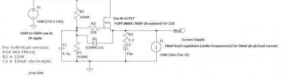
A slow rise Damper diode like 6D22S, PY500, 6CJ3 etc is really the best. But if you don't want to use them, you could adapt the standard FET passive regulator. With 220K and 100uF at the gate position, you could get a very slow start.
Or, you could use a smaller capacitor and a small (mains-rated) switch from the FET gate to ground. With the switch closed, the B+ does not appear.
This circuit can power preamps directly, and will reduce ripple and noise very effectively, as well as give slow rise time.
With power amps, the circuit would need a very large FET to supply the anode current. But in many cases there is no need to interrupt the anode supply.
If your power amp uses pentodes, simply apply B+ to the anodes at any time, but delay the screen voltage VG2 using the circuit above. With zero volts on VG2, you are protected from any cathode stripping OR van de Weijer effect, because the electric field at the cathode will be effectively zero.
With fixed-bias amps, you can use a negative-voltage startup FET circuit that applies a very large negative bias while the heaters/filaments warm up. Again, the aim is to reduce the electric field at the cathode while it warms up.
With auto-bias, and triodes, you have to delay and ramp the anode supply. You could use a large FET, but I think that a damper, even if only a single diode in the dc supply line, is the best solution.
Attachments
So the conclusion is that there should be some delay and also it is preferable to gradually apply B+. Correct?
So the practical question would be - how would you suggest to accomplish it in a case of SS rectifier? Can you point me to a good (preferably simple) solution that would gradually apply B+ and that could be constructed without thermionic valve components?
Thank you!
A simple two-stage circuit that applies B+ through a suitable resistor followed by simply shorting the resistor with a switch or relay.
Even when I use slow tube rectifiers like damper diodes I still use a delayed slow start arrangement. Damper diodes are tough, but they will cathode strip just like any other tube. While cheap, they aren't free, and as they degrade your PS will get soggier due to the reduced cathode emission. I like tube rectifiers in SE amps mainly because they are completely noiseless. I will probably try SiC Schottky's in my next PP project though...
Despite the existence of sizable caps in most PSs, my experience using a B+ switch is that it comes up VERY quickly (OK, in human terms, not necessarily electronic terms). So based on this discussion so far, while there's debate at the molecular or atomic level, there does seem to be little harm in delaying B+ and potential benefit, even to a hot tube. This is DIY after all, so I for one don't mind a little extra cost and complication (I DO mind a very costly approach though, as I'm a miser at heart!). Maybe I need to look at damper diodes and do some RC calculations to look at my PSs designs?
Heaters, while they do seem to "warm up" relatively slowly, would seem to be hit by high current during that warm up phase, so I also see value in slowing that. I wonder if one approach might be to develop a gradual heater supply and then monitor current in the heater circuit and start a delayed and gradual application of B+ once heater current settles to the expected level? No idea how to do that yet though.
Heaters, while they do seem to "warm up" relatively slowly, would seem to be hit by high current during that warm up phase, so I also see value in slowing that. I wonder if one approach might be to develop a gradual heater supply and then monitor current in the heater circuit and start a delayed and gradual application of B+ once heater current settles to the expected level? No idea how to do that yet though.
Heaters, while they do seem to "warm up" relatively slowly, would seem to be hit by high current during that warm up phase, so I also see value in slowing that. I wonder if one approach might be to develop a gradual heater supply and then monitor current in the heater circuit and start a delayed and gradual application of B+ once heater current settles to the expected level? No idea how to do that yet though.
That's quite straightforward to do, provided you can accept running your heaters from dc. OF course, this is helpful when the signal levels are very low, or if you are using directly-heated valves, anyway.
provide a raw dc supply, and apply to the heater/filament via constant current supply (CCS). Of course, simple 2-transistor CCS is perfect here. This will prevent surge currents in the heater, and cause the voltage across the heater to rise very slowly. A power tube can take 1 minute to get to rated voltage, when CCS fired. Now, attach a low power comparator [LM393 etc], to detect when the heater has reached 90% rated voltage. Then, opto-couple a signal to the slow-start FET circuit posted earlier.
NTC Thermistor + Relay can reduce surge very well. I use a Microcontroller to program On/Off sequence. I had design a integrated tubes protection circuit to some Tube amplifiers manufacturer. It combine many function together.Microcontroller control autobias , On/Off sequencer , Over current protection. It turn on Filament first , delay , turn on B+ but series with a relay of which parallel with a NTC. This relay contact turn on after few second later. It can reduce surge to a very low level. This circuit also can avoid short circuit tubes burn components. Autobias can adjust bias to +-1ma and no side effect on sound quality. It may be will release to DIY market later.
NTC Thermistor + Relay can reduce surge very well. I use a Microcontroller to program On/Off sequence. I had design a integrated tubes protection circuit to some Tube amplifiers manufacturer. It combine many function together.Microcontroller control autobias , On/Off sequencer , Over current protection. It turn on Filament first , delay , turn on B+ but series with a relay of which parallel with a NTC. This relay contact turn on after few second later. It can reduce surge to a very low level. This circuit also can avoid short circuit tubes burn components. Autobias can adjust bias to +-1ma and no side effect on sound quality. It may be will release to DIY market later.
And here I thought I was the only guy who used uC's to control power, bias, and protection functions on a tube amp 😀
I use a very simple combination with NTC thermistor and a relay. No active components at all. The raw heater AC goes thru the thermistor to the heaters. The single rectifier diode goes to a capacitor and the relay coil. On turn-on the heaters are cold and low resistance while the thermistor has high resistance limiting the current. As the heaters warm up (and the thermistor) the resistances change and the voltage over the heater and thus relay coil increase. When the relay coil get about 5volts it switches on and shorts out the thermistor. Works great and very few parts😉
Btw, according to Tomer ('Getting the most out of vacuum tubes') heater inrush is the dominant failure mechanism. The ion bombardment and cathode srtipping is more a theoretical mechanism and should be lower on the list. So if you have delays on b+ and nothing to limit heater inrush current youve kinda missed the bullseye.
I use a very simple combination with NTC thermistor and a relay. No active components at all. The raw heater AC goes thru the thermistor to the heaters. The single rectifier diode goes to a capacitor and the relay coil. On turn-on the heaters are cold and low resistance while the thermistor has high resistance limiting the current. As the heaters warm up (and the thermistor) the resistances change and the voltage over the heater and thus relay coil increase. When the relay coil get about 5volts it switches on and shorts out the thermistor. Works great and very few parts
Hmmmm. I like this. Simple and seemingly effective. I've used inrush thermistors before, usually for B+ though. I like the use of the relay to switch out the thermistor. Relay is robust in this use?
Yes ! Relay is very reliable . It only very low Voltage differnce between it.Hmmmm. I like this. Simple and seemingly effective. I've used inrush thermistors before, usually for B+ though. I like the use of the relay to switch out the thermistor. Relay is robust in this use?
- Home
- Amplifiers
- Tubes / Valves
- To switch B+ or not?