Hi again everyone,
I completed soldering the first pcb and have found my first deadend - I am trying to adjust quiescent current, but am reading 0mv regardless of trim poti settings.
I have:
* correct input voltage (measured) and correct direct current out of PSU (measured)
* shorted input
* nothing attached to output
* everything remains cool, no smoke as well 😉
* measuring DC mV between MP1 and MP2
* there is 0mV, I can turn the trim from stop to stop and it will not change
Anything obvious I am doing wrong? Would it make sense to attach a speaker and source to check if the amp is doing anything or could this damage anything?
Attachments

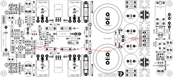
First question: did you solder the wire from the Frontends "Small Signal GND" to the backends GND? Have a look into the Builder's Manual!
This connection has to be wired manually!
Best regards - Rudi_Ratlos
This connection has to be wired manually!
Best regards - Rudi_Ratlos
Oh... Rudi, thanks for the quick answer, indeed I read the manual about 100 times and failed to do just this.
The manual lists another board revision here, are the locations in the marked pcb correct? For simplicity I would prefer to solder them on component side, I'd rather not split the transistors from the heat sink again...
The manual lists another board revision here, are the locations in the marked pcb correct? For simplicity I would prefer to solder them on component side, I'd rather not split the transistors from the heat sink again...
Attachments
This was it rudi!
I was able to adjust quiescent current perfectly now, also DC offset is about 6mV.
I then plugged in a source and speaker and was greeted with terrible 50hz hum. A quick depression and I remembered that one of the input cables lying around was defective and I managed of course to grab just this cable...
Replaced by another cable and 😱 - It works!
Now on to finish the second pcb..
Thank you all for your help so far, this has been a very exciting build for me as a soldering-newb.
If anyone interested i sell my finished SYMSYM black beauty modules.
Thanks for this beautiful boards Rudi!
http://www.diyaudio.com/forums/swap-meet/312137-sale-symasym-black-beauty-completed.html#post5182135
Thanks for this beautiful boards Rudi!
http://www.diyaudio.com/forums/swap-meet/312137-sale-symasym-black-beauty-completed.html#post5182135
Issues
Hi guys,
I finally found time to finish the build, but I stumbled into an issue.
The amps were working fine for two weeks on the bench without a case. Last week I finally put them into the case and everything was working fine there as well (only tested quickly).
When putting on the front of the case (not connected to anything..) I heard a loud pop from the left channel followed by 50hz noise. I quickly disconnected power, but the problem persists. I have unmounted loudspeaker and input terminals from the case as I thought I might have grounded the input or shorted something, but it remains.
Very grateful for answers!
Hi guys,
I finally found time to finish the build, but I stumbled into an issue.
The amps were working fine for two weeks on the bench without a case. Last week I finally put them into the case and everything was working fine there as well (only tested quickly).
When putting on the front of the case (not connected to anything..) I heard a loud pop from the left channel followed by 50hz noise. I quickly disconnected power, but the problem persists. I have unmounted loudspeaker and input terminals from the case as I thought I might have grounded the input or shorted something, but it remains.
- both channels show correct voltage, Power and Frontend LEDs are on.
- Channel L goes into Loudspeaker protection, Channel R plays fine
- at some point the protection switches off and L plays faint music and a very loud 50hz hum. At this point channel R goes quiet. Also, if I touch the playback device (mobile phone, no connection to mains power) I can hear a change in hum.
- If I disconnect the L input, there is only hum on L and R keeps playing fine. However, if I disconnect R input the right channel still faintly plays music! (cross from the L channel?)
Very grateful for answers!
Hello Seldon,
are you sure that there is no Ground loop or something like that. But way did the left Chanle run in protection?
Try to use each Board separately at your power supply.
Regards
Thomas
are you sure that there is no Ground loop or something like that. But way did the left Chanle run in protection?
Try to use each Board separately at your power supply.
Regards
Thomas
Thanks for the help!
There should not be a ground loop, as I did not change anything from working to non-working. I will make pictures Wednesday, when I'm back at work. I will try separate power supply tests then as well.
There should not be a ground loop, as I did not change anything from working to non-working. I will make pictures Wednesday, when I'm back at work. I will try separate power supply tests then as well.
Hi Guys,
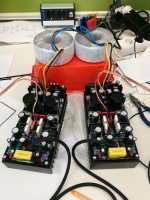
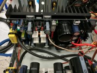
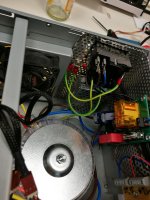
as promised some pictures of the build. Could be neater, I know 😉
The basic setup is quite easy. Power in goes into a soft power-on by diy-audio. From there to the two transformers and then into the symasym power section.
Input is directly soldered onto the pcb, output goes through the speaker protection on the black beauty.
Too much work today, I will disassemble and inspect tomorrow. Maybe an input wire has come loose or the ground-cable on the pcbs? I hope nothing is really damaged...
Attachments


One thing I noticed further:
All four leds are on as soon as I plug in power. As soon as I unplug them, the two LEDs on the left PCBs side stay on, while the right side LEDs go out immediately. Could this be an indication for a short on the right pcb side?
All four leds are on as soon as I plug in power. As soon as I unplug them, the two LEDs on the left PCBs side stay on, while the right side LEDs go out immediately. Could this be an indication for a short on the right pcb side?
Hi guys,
sorry for the message spam, but I can't edit my posts after some time.
I did some more measurements today with help of a colleague. I was mistaken with my DC output measurement (was measuring after speaker protection...).
My amp has -23VDC on the speaker output, measured against GND! 😱
Our current idea is, that one of the transistors is defective, what do you think?
Hi Seldon,
I don´t think that one of the transistors must be defective. Probably the Transistors (including the Drivers) on the negative rail are not on their working point. About 10V are drop down at the power transistors.
Regards
Thomas
I don´t think that one of the transistors must be defective. Probably the Transistors (including the Drivers) on the negative rail are not on their working point. About 10V are drop down at the power transistors.
Regards
Thomas
Thanks for the info, any idea on how to debug this? Would it be better to keep it mounted to the heatsink to make measurements or should I disassemble and look for bad solder points?
hi everyone
such a beautiful design
can I have Gerber and drill files?
is it too bad to use ST semiconductors 5200 complementary?
such a beautiful design
can I have Gerber and drill files?
is it too bad to use ST semiconductors 5200 complementary?
Help needed :/
Hi everyone,
my work kept me too busy these past weeks, I finally found time to do some measurements yesterday.
Setup was with bridged input and a 4ohm high-load resistance on the output (didn't want to burn my speaker). All measurements were taken in DC against Ground.
Do these values make any sense to you? My initial guess is, that Q1 or Q2 is defective, since there is dc voltage already present in the input path? I'm no electrical engineer though.
All help is highly appreciated!
Attachments
more
Hi guys,
so I have been told by PM, that I am asking too much of you. I know, fixing someone else's mistakes is a pain in the ***, especially, if that someone is a new member. Maybe I was also not clear enough, I am not asking for someone to give me the solution (although that would be nice), but rather hints/ideas on how to proceed.
At this point I could throw the whole thing into the trash and quit, but I choose to try and fix it anyways. I will post progress here anyways, maybe at some point someone has an idea or hint.
Current state of progress:
* I have unmounted the defective amp from the case and test it by itself.
* I have checked again, that not concact is between the heat sink and other components (there is none).
* I have measured all passive components in the input path for correct values (in reference to the functioning channel). They seem ok.
I am currently trying to focus on the problem of dc voltage at the input side. When measuring with open input there is ~2VDC at the input connector. This (so far my theory) is then further on amplified by the power transistors. From my understanding, the voltage can only come from Q1 or Q2. I have therefore ordered a new set of 2SK170 and will replace them in the coming days.
Also, I have thought again about the reason for this issue. My current idea here, is that when mounting everything into the case, I have shorted the input and output side, thus giving an amplified signal into the input and overloading it.
Ideas/Comments? Should I change Q3/4 as well, while I'm at it? Or am I completely on the wrong path? Unfortunately the pcbs are not sold anymore, or I would just build a new one...
As always, help of any kind is highly appreciated.
Layout files
Hi guys,
nice living Project i have found here. I plan to build my first diy amp and i live near Berlin Germany. I hope i am right here. is this ok if i ask for pcb layout files? I want to etch my own boards at home, dont Need a bigger amount or Long waiting time for boards from China
Hi guys,
nice living Project i have found here. I plan to build my first diy amp and i live near Berlin Germany. I hope i am right here. is this ok if i ask for pcb layout files? I want to etch my own boards at home, dont Need a bigger amount or Long waiting time for boards from China
- Home
- Group Buys
- TO-3 SYMASYM