One more SymAsym is running
Hi Rudi,
Thank you 🙂 for these wonderful SymAsym boards I have got from you !
The first channel did run at once, following your procedure 😉 of course, without any problem, and I have measured the DC value at the output as <-1mV ... 😀. I did not expect to get a negative number, but it is so small 🙂 that I am happy with it.
I will now populate the second board and when all will be running OK, I will post some photography of the baby. But before I will hear some music with both channels running. I think that my friend will be more than happy with such a good amplifier !
The explanations you have provided to all of us were outstanding and really a very good and friendly help as every problem that might occur is solved inside.
Thank you Rudi 😀 !
Best regards
rephil
Hi Rudi,
Sorry, I was so euphoric yesterday due to the good results with my build that I have written the following : "DC value at the output was <-1mV", it should obviously be understood that "the absolute value was and remained <1mV" ...
I should sometimes follow your suggestions with more care 🙄, using a smaller 😱 bottle of very good italian 😀 wine in order to perform what you did write in your "Benutzerhandbuch" (Instructions for use) : "Yetzt einen kräftiger Schluck Whisky (oder Weissbier) - und Power On" (Now a huge draught of Whisky (or white beer) - and Power On) ... I had neither whisky nor white beer at hand, so as always in diy I used what I had home - italian wine -, willing more than enough help 😉 ...
Thank you again Rudi 😀😀 : I am more than happy 🙂 with this SymAsym.
Best regards
rephil
Rephil, thank you for your kind words!
I know myself that the SYMASYM is a real gem: easy and uncomplicate to build, it does not need any fancy
components, and it sounds amazingly well, especially, if you you have gone for the TO3 - version.
I have ordered a small couple of my current SYMASYM-TO3 - PCBs a minute ago (see attached image).
I have 3 PCBs left.
If anybody wants to have these 3 PCBs: send me a PM.
I will offer to this one an additional PCB as well. SURPRISE!
Best regards - Rudi_Ratlos
Attachments
Rephil, thank you for your kind words!
I know myself that the SYMASYM is a real gem: easy and uncomplicate to build, it does not need any fancy
components, and it sounds amazingly well, especially, if you you have gone for the TO3 - version.
I have ordered a small couple of my current SYMASYM-TO3 - PCBs a minute ago (see attached image).
I have 3 PCBs left.
If anybody wants to have these 3 PCBs: send me a PM.
I will offer to this one an additional PCB as well. SURPRISE!
Best regards - Rudi_Ratlos
Hi Rudi,
You got mail.
rephil
Hello,what modification's i need to make to the amp if i want to put another pair of mjl and my power suply is +- 56vd dc(2x56v dc),i made some schematics to see if they are good or not,thank you !
Image - TinyPic - Free Image Hosting, Photo Sharing & Video Hosting
New Images - TinyPic - Free Image Hosting, Photo Sharing & Video Hosting
New Images - TinyPic - Free Image Hosting, Photo Sharing & Video Hosting
Image - TinyPic - Free Image Hosting, Photo Sharing & Video Hosting
New Images - TinyPic - Free Image Hosting, Photo Sharing & Video Hosting
New Images - TinyPic - Free Image Hosting, Photo Sharing & Video Hosting
Hi Rudi,
I could not resist to it ... I wanted to hear what kind of quality of the music could be produced by the first channel I have built of the SymAsym 😱.
It is fantastic with good bass frequencies, sweet high, it is also very powerful 😀 😀. All that gives really great satisfactions ... 😀. Thank you Rudi for this SymAsym TO3 😀, I enjoy the music, and my friend that will get the amp has no idea of how good this power amp is 😉😀.
BTW, it is time - you should do it please - to organise another group buy for this outstanding amp . I understand now why some of us did buy so many boards from you : it is the best amp that I have here ! I didn't know 🙁...
The only drawback is the THD 😱 ... well the spectrum has mostly only the 2nd and 4th harmonics, but for my taste, I should like to get also "wonderful numbers" for the THD ... But the sonics resulting is really top notch! I don't want to hear anything else ...
Thank you again Rudi 😀.
Best regards
rephil
I could not resist to it ... I wanted to hear what kind of quality of the music could be produced by the first channel I have built of the SymAsym 😱.
It is fantastic with good bass frequencies, sweet high, it is also very powerful 😀 😀. All that gives really great satisfactions ... 😀. Thank you Rudi for this SymAsym TO3 😀, I enjoy the music, and my friend that will get the amp has no idea of how good this power amp is 😉😀.
BTW, it is time - you should do it please - to organise another group buy for this outstanding amp
. I understand now why some of us did buy so many boards from you : it is the best amp that I have here ! I didn't know 🙁...The only drawback is the THD 😱 ... well the spectrum has mostly only the 2nd and 4th harmonics, but for my taste, I should like to get also "wonderful numbers" for the THD ... But the sonics resulting is really top notch! I don't want to hear anything else ...
Thank you again Rudi 😀.
Best regards
rephil
Would to order PCB's if not to lates
I would like following from the TO-264 / TO-3PBL SYMASYM Group Buy:
(1) Four (4) AMP PCB's
(2) Four (4) SKPR PCB's
(3) Eight (8) PSU PCB's
Let me know if it's not to late. Take care.🙂
I would like following from the TO-264 / TO-3PBL SYMASYM Group Buy:
(1) Four (4) AMP PCB's
(2) Four (4) SKPR PCB's
(3) Eight (8) PSU PCB's
Let me know if it's not to late. Take care.🙂
Any news about Group Buy's for TO-264 / TO-3PBL SYMASYM PCB's?
Any news about a future Group Buy's for TO-264 / TO-3PBL SYMASYM PCB's?
I'm interested in both versions.😕
Any news about a future Group Buy's for TO-264 / TO-3PBL SYMASYM PCB's?
I'm interested in both versions.😕
Gentlemen, SYMASYM-friends, I have received several feedbacks concerning my currently offered TO3/SYMASYM - PCBs (Rephil, Jorge, ... for example), telling me that my SYMASYM sounds best
(compared to nearly every competitor - DIY-Amplifier ) and that an audible improvement will not be possible 😉 .
Will it not be?
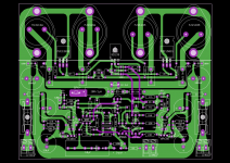
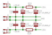
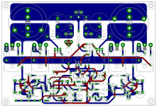
According to my experience: an amplifier sounds at is best, if the PSU (the reservoir CAPs !) is mounted as close as possible to the consumers (the output transistors),
and therefore did a "final" layout of the (my) SYMASYM.
http://abload.de/img/njw-symasym_v3-topviedasww.png
I have mounted the big reservoir CAPs on top of the PCB, the output-transistors (NJW-transistors, the MJE-drivers and the TEMPCO - BD139) being mounted below the PCB and hope: this is it!
The Signal-GND (on the bottom of the PCB) will not be affected by the "noise" inserted by charging / dis-charging the Solid-GND (on top of the PCB).
I am sorry that my Gerber-File-Viewer (GERBV) is not able to present the layout of this PCB correctly. There are a lot of horizontal black, small tracks to disturb the overall view!
The PCB incorporates CAP-Multipliers to provide smoothed frontend-voltages (consuming less than 15mA per rail) - as you can see (for example) on the bottom right of the PCB.
I will go and order 10 of these PCBs on the the coming weekend. Six of them are already reserved.
If somebody of you will this PCB a try (since they are prototypes) and wants to have it (price is 12€ per PCB - shipping is 3.45€ worldwide): 4 of these PCBs are not yet reserved.
Best regards - Rudi_Ratlos
P.S.: The size of the PCB is 150x100mm.
(compared to nearly every competitor - DIY-Amplifier ) and that an audible improvement will not be possible 😉 .
Will it not be?
According to my experience: an amplifier sounds at is best, if the PSU (the reservoir CAPs !) is mounted as close as possible to the consumers (the output transistors),
and therefore did a "final" layout of the (my) SYMASYM.

http://abload.de/img/njw-symasym_v3-topviedasww.png
I have mounted the big reservoir CAPs on top of the PCB, the output-transistors (NJW-transistors, the MJE-drivers and the TEMPCO - BD139) being mounted below the PCB and hope: this is it!
The Signal-GND (on the bottom of the PCB) will not be affected by the "noise" inserted by charging / dis-charging the Solid-GND (on top of the PCB).
I am sorry that my Gerber-File-Viewer (GERBV) is not able to present the layout of this PCB correctly. There are a lot of horizontal black, small tracks to disturb the overall view!
The PCB incorporates CAP-Multipliers to provide smoothed frontend-voltages (consuming less than 15mA per rail) - as you can see (for example) on the bottom right of the PCB.
I will go and order 10 of these PCBs on the the coming weekend. Six of them are already reserved.
If somebody of you will this PCB a try (since they are prototypes) and wants to have it (price is 12€ per PCB - shipping is 3.45€ worldwide): 4 of these PCBs are not yet reserved.
Best regards - Rudi_Ratlos
P.S.: The size of the PCB is 150x100mm.
Attachments
Last edited:
what version are you referring to?concerning my currently offered TO3/SYMASYM - PCBs (Rephil, Jorge, ... for example), telling me that my SYMASYM sounds best
This new layout does not look like a To3.
Are those To247 or To264 Power Devices?
Andrew, I am referring to the SYMASYM-version as show in post #764.
It uses 2 pairs of TO3 - MJ21195G/MJ21196G as output transistors.
The SYMASYM sounds very well with those TO3-transistors.
My current effort is to include part of the PSU (reservoir-capacitors) on the amplifier's PCB.
Since I couldn't come up with a reasonable layout using TO3s, I changed to NJW0281G/NJW0302G (TO-3P case) and will mount them beneath the PCB.
This way the "hot area" - charging and de-charging the reservoir caps - is on top of the PCB and does not (this is what I think) affect the "small signal" area,
which is on the bottom of the PCB and which is fed by 2 cap-multipliers.
Best regards - Rudi_Ratlos
P.S.: All of the "new" PCBs are already reserved.
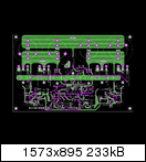
Maybe better that the left 22R resistor has a little more space like the right one?
Nice design Rudy!!
Nice design Rudy!!
Loek: the 22R resistors around the input are only used, if you operate the SYMASYM from an "active PreAmplifier (Gain >0)" .
In case you use a passive PreAmplifier (Source Selection + potentiometer), the 22R resistors are replaced by wires (will be bridged).
Best regards - Rudi_Ratlos
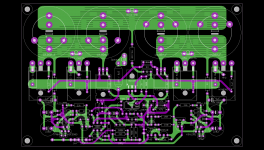
P.S.: In the meanwhile I have the enhanced (?) the on-top reservoir-capacitor layout by a new one, since I have had some luck and "inherited" a couple of "ELNA for AUDIO caps" for a very nice offering.
I wonder, how the NJW0 transistors will sound as compared to the TO3.
Best regards - Rudi_Ratlos
In case you use a passive PreAmplifier (Source Selection + potentiometer), the 22R resistors are replaced by wires (will be bridged).
Best regards - Rudi_Ratlos
P.S.: In the meanwhile I have the enhanced (?) the on-top reservoir-capacitor layout by a new one, since I have had some luck and "inherited" a couple of "ELNA for AUDIO caps" for a very nice offering.
I wonder, how the NJW0 transistors will sound as compared to the TO3.
Best regards - Rudi_Ratlos
Attachments

Last edited:
Patrick: I have given my word to somebody and will show him that the sound of the SYMASYM will be improved (will be "quicker"), if you mount the PSU-reservoir-CAPs
very close to the consumers (the output transistors).
Best regards - Rudi_Ratlos
P.S.: I will not offer this layout as a "Group-Buy - layout". I only did it to approve my assumption.
very close to the consumers (the output transistors).
Best regards - Rudi_Ratlos
P.S.: I will not offer this layout as a "Group-Buy - layout". I only did it to approve my assumption.
Last edited:
- Home
- Group Buys
- TO-3 SYMASYM