Ryan, I have sent you the LTSpice - model of the SYMASYM per EMail.
Maybe it can assist debugging your problem.
Best regards - Rudi_Ratlos
Maybe it can assist debugging your problem.
Best regards - Rudi_Ratlos
Some weeks ago I finished my SYMASIM amp. Still to finish the case but it sounds superb... It is a litlle diferent the power suply is +-43V, the zeners are 39V and for CAP multiplier i used BD139/140. Bias procedure was easy 2SK 170BL matched 10mA. MP1-MP2 24,0mV, DC offset 0,2mV and 0,3mV.
Then I soldered the second pair and enjoyed the music...
I noticed that the amp is running a bit hot, ok it´s summer the room temp was 28°C....
Yesterday I separate my test heatsink and noticed that one chanel is much hoter. 57°C on mosfets and 49°c on the heatsink, the other 43°C mosfet, heatsink 37°C. today I measure again the MP1-MP2 points on the hoter chanel I have 49,5mV and the colder 39,6mV, Dc offset is 0,3mV on the hoter and 0,2mV on the colder. the amps idles around 280mA the hoter and 220mA the colder. Input is shorted when I measure.
Do I have to readjusted the trimpot again?
Attachments


Ooops update #1
Reminder of the problem: I had loud static output after returning to my amp whilst letting it play unattended. I wasn't around when things went awry.
Here are some of the measurements I made:
As a precaution, I checked that there were no shorts between transistors and the heatsink. All was fine.
So then I powered up the PSU...
- Rails:+/- 38 VDC (unloaded, my mains fluctuates a lot, and my rails are in the 37-38+ range). I have +/- 25VAC primary transformer.
Then I powered the Amp board:
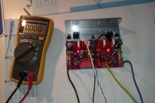
With input grounded:
- Vtp1 to Vtp2 is 24 mV
- Vdc across output 18 mV
Any ideas? Is it possible that because of my higher rail voltage, the front end regulation was toasted?
I have Rudi's LTSpice sim (Thanks Rudi!) , but I do not have an immediately easy way to run it. So, I don't have voltages to check yet.
Thanks
Ryan
PS: Yes, I have tested the amp with another pre-amp and set of speakers, so I know that the problem resides with the amp.
Reminder of the problem: I had loud static output after returning to my amp whilst letting it play unattended. I wasn't around when things went awry.
Here are some of the measurements I made:
As a precaution, I checked that there were no shorts between transistors and the heatsink. All was fine.
So then I powered up the PSU...
- Rails:+/- 38 VDC (unloaded, my mains fluctuates a lot, and my rails are in the 37-38+ range). I have +/- 25VAC primary transformer.
Then I powered the Amp board:
With input grounded:
- Vtp1 to Vtp2 is 24 mV
- Vdc across output 18 mV
Any ideas? Is it possible that because of my higher rail voltage, the front end regulation was toasted?
I have Rudi's LTSpice sim (Thanks Rudi!) , but I do not have an immediately easy way to run it. So, I don't have voltages to check yet.
Thanks
Ryan
PS: Yes, I have tested the amp with another pre-amp and set of speakers, so I know that the problem resides with the amp.
In a previous post, I believe Rudi suggests to re-set the bias after adding the second set of output transistors. In my case (TO-3) I found that I needed to adjust the bias a little bit... on the order of a couple of mV, after adding the second set of TO-3s. Nothing dramatic.
If I am incorrect or have mis-understood, please let me know.
If I am incorrect or have mis-understood, please let me know.
Some weeks ago I finished my SYMASIM amp. Still to finish the case but it sounds superb... It is a litlle diferent the power suply is +-43V, the zeners are 39V and for CAP multiplier i used BD139/140. Bias procedure was easy 2SK 170BL matched 10mA. MP1-MP2 24,0mV, DC offset 0,2mV and 0,3mV.
Then I soldered the second pair and enjoyed the music...
I noticed that the amp is running a bit hot, ok it´s summer the room temp was 28°C....
Yesterday I separate my test heatsink and noticed that one chanel is much hoter. 57°C on mosfets and 49°c on the heatsink, the other 43°C mosfet, heatsink 37°C. today I measure again the MP1-MP2 points on the hoter chanel I have 49,5mV and the colder 39,6mV, Dc offset is 0,3mV on the hoter and 0,2mV on the colder. the amps idles around 280mA the hoter and 220mA the colder. Input is shorted when I measure.
Do I have to readjusted the trimpot again?
Ryan, if you have activated the onboard-CAP-multiplier (if you did not set the jumper-cap), the zener diode delimits
the frontend-voltage to 36VDC. You need not worry then.
Moreover: 38VDC is not a voltage to worry about.
I recommended to adjust the quiescent current / BIAS with only one MJ21196 / MJ21195 being soldered to minimize the dammage,
in case you have done a error while soldering the PCB.
It is then required to do the adjustment once more, after you have soldered the 2nd pair of MJ21196 / MJ21195.
The usage of LTSpice is very simple. Download the current version, open the SYMASYM.asc file that I sent you,
and then click on the icon "RUN" on the toolbar.
Position the cursor on any component / track on the schematics and click to plot the voltage, amount of current, ...
According to my experience a crackling noise has to do some with a mechanical error (f.e. a short between the ALU profile
and the output transistors, something getting hot after a while, ...).
I hope that you are able to find the error.
Best regards - Rudi_Ratlos
HI,
im planning to build a bass amplifier(with 2x8" speaker), and i saw this thread, reading all the post i think this is a good amplifier, but now im not sure if i can use it to my bass guitar, and it does not have a pre amp...
can i use a 24-0-24 trnasformer?
and also i cant understand the different kinds of capacitor that was use in the symasym,
thats why im confused to which should i use...
Yoyoy, I do not know the requirements that a bass guitar amplifier must have.
The SYMASYM is a Class A/B amplifier, and it does not have a pre-amplifier onboard.
About capacitors: there have been some questions about the value of the input capacitor C1.
The job of C1 is to block DC voltage. You can take any value from 3.3µF - 10µF for C1.
You can of course use your 24VAC - 0 - 24VAC transformer.
Best regards - Rudi
Previous version PCB's for the TO-3 SYMASYM
Does anyone have two or more of the previous version of the TO-3 SYMASYM
PCB's. I missed the last group buy. Let me know.😡
Does anyone have two or more of the previous version of the TO-3 SYMASYM
PCB's. I missed the last group buy. Let me know.😡
@mcds: the PCB-layout already includes CAP-multipliers to provide smooth and stable voltages for the frontend, and the CAP-multipliers
are doing a very good job.
@Rephil: I measured my TO3s with a collector current of 100mA (adjusted by the CCS of my test-rig).
The main function of the input capacitor is to block DC voltage.
I myself am using a 3.3µF Vishay MKT.
Best regards - Rudi_Ratlos
Rudi, strictly speaking this is not cap multiplier but a regulator with no feed back and with stable utput voltage. A cap multiplier output follows slow changes of the input voltage.
BR Damir
You are of course right, Damir.
I am using a very simplistic implementation of a CAP-Multiplier.
It has 2 jobs to do:
- 1st: to generate a smooth and stable frontend voltage (and it does this quite well - but can even be made better, f.e. by a shunt)
- 2nd: to restrict the frontend voltage to +/- 36 VDC to not destroy your preciously matched differential input amplifier (f.e. 2SK170)
I am currently thinking about adding a "cross-distortion minimizer" (Douglas Self calls this: "XD - Technology" (Chapter 11 of his amplifier - cookbook).
I know that he has a patent pending upon his idea.
If any moderator is reading this post: may I talk about this improvement (?) in plain text or am I not allowed?
Best regards - Rudi_Ratlos
Yoyoy, I do not know the requirements that a bass guitar amplifier must have.
The SYMASYM is a Class A/B amplifier, and it does not have a pre-amplifier onboard.
About capacitors: there have been some questions about the value of the input capacitor C1.
The job of C1 is to block DC voltage. You can take any value from 3.3µF - 10µF for C1.
You can of course use your 24VAC - 0 - 24VAC transformer.
Best regards - Rudi
about the caps, what i was asking was what kind of cap is C2 and C3? and how are they different? can you also suggest any pre-amp that i can attach to symasym...
-yoyoy
@Yoyoy: I am using a 100nF WIMA cap as C2 and a Cornell/Dublier 100pF as C3.
I do not use an "active" pre-amplifier.
I am using my VCPre passive pre-amp:
http://www.diyaudio.com/forums/group-buys/237302-versatile-comfortable-passive-pre-amp.html
for my SYMASYM.
Best regards - Rudi_Ratlos
I do not use an "active" pre-amplifier.
I am using my VCPre passive pre-amp:
http://www.diyaudio.com/forums/group-buys/237302-versatile-comfortable-passive-pre-amp.html
for my SYMASYM.
Best regards - Rudi_Ratlos
Yoyoy, MPSA18 is a good substitute or BC550C (be aware about reversed pinout then).
Best regards - Rudi
Best regards - Rudi
Help please
All,
My woes are outlined up above.... But last testing, Bias 24 mV, DC offest within spec. Amp was a massive AM radio receiver. I turned it off quickly to avoid toasting things.
Given that I had plenty of small signal transistors on hand, I decided to replace them all... it is an expedient approach to fixing things. I understand, not very sophisticated nor elegant. Regardless... now that I have all new small signals, the bias comes up solid at 24 mV as before. However, I'm now looking at about 1.2V of DC offset on the output.
Update: after 15 minutes or less, it's now to 0.9 VDC on the output.
That is with the input grounded. I DO have matched to 2SK170s on the input. Where else do I need to 'match' the small signal transistors more closely to reduce the DC offset? Or is there something else I'm missing.
Note, I also replaced the input capacitor with another MKP type.
Thanks,
Ryan
Last edited:
update
The Vdc offset settled down to about 170mV, well outside of spec. So ...
I had a bunch of MPSA18 sitting around. I quickly matched a pair for Hfe and installed those (at 180degrees to the sk170).
====INCORRECT
All seems okay. Vdc is now a fraction of a mV (i.e. mostly zero.) I've set the bias to ~25.5 mV as I have larger heatsinks. I will let it settle for a few hours and see what happens. Then maybe some music.
=====INCORRECT.
It helps to have the output connected to the speaker terminals on the chassis... brilliant..
OFFSET is still a couple of hundred mV. So I will try to do as Andrew suggested as well as run the Sim to get voltages around the circuit. I was too anxious in hoping for a quick fix. How fussy is the "C" rating in the BC560C position?
Ryan
Last edited:
Enough for today
My weekend is mostly over, so I've got to quit for now.
With MPSA18, 25mV bias setting, 300mV of VDC on the output:
Of the measurements I've made, there doesn't seem to be anything extraordinarily out of whack but ...
Emitter currents for the 2n5551 (measured across the 150R resistors)
Current through R12 = (.362V/150R) = 2.41 mA into emitter of Q9 (Q11 on sim)
Sim says: 2.48 mA
Current through R11 = (.343V/150R) = 2.28 mA to emitter of Q8 (Q13 on sim)
Sim says 2.44 mA
Current thru 47K resistor that connects to collector of 2N5551:31.9 uA
Simulation says: 18.2 uA ... That seems to be a problem
Current thru 47K resistor that connects to collector of 2N5401: 19.8 uA
Simulation says: 22.4 uA
Current thru 68R resistor that connects to emitters of 2N5401: 4.8 mA
Simulation says: 5 mA
Do these give a hint as to what might be amiss?
Thanks!
Ryan
Ryan, a well-matched SYMASYM shows a DC-Offset of < 5mV. My own one has an offset of about 1mV.
Whenever I read about a SYMASYM - DC-Offset problem in the German DIY-forum and then read the
conclusion, it is one of 3 reasons:
1 - solder error (short)
2 - wrong small transistor used
3 - reversed pinout of small transistor used
Your findings (2N5551) point to this direction as well.
Best regards - Rudi
- Home
- Group Buys
- TO-3 SYMASYM