The first sweet taste of success
The first challenge today was to get the wrongly inserted 2n5551 right, I did not have any desoldering wick left.
So I had to revert to a desoldering pump and brute force, I did have two spare pairs of matched 2n5551 and used these.
Removed the jumpers, to activate the CAP-Multiplier
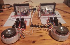
Second: Getting the L profile and the power transistors in place.
Rudi, thanks for the tip to use some shrink tubing, that is a live saver.
I did not use paper as insulator between L profile and PCB, I did have some extra TO-3 micas ( 8 ) and used these.
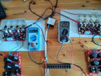
Third: Power on, no blown fuses, no smoking parts, all OK.
Forth: Set the bias current, R channel had the DMM on the wrong setting, so adjusted too high for a few seconds, turned all the way back, set the DMM the right position, and re-adjusted, set value to 29 mV.
L channel, made sure the DMM was set to the right position 🙂) no problem setting to adjust to the same 29 mV. it creeps up slowly, and the power transistors get warm (not hot). R channel gets warmer then the L channel.
I did power down after about 10 minutes, (L profiles where warm, but I did not have a problem handling them with my bare hands).
I want to attach the heat sinks first before continuing, and make a temporary backplate for the input connectors and speaker terminals.
So I expect, that next weekend it will play some music.
Rudi, thanks for the PCB's it is a pleasure to make a system with them.
The first challenge today was to get the wrongly inserted 2n5551 right, I did not have any desoldering wick left.
So I had to revert to a desoldering pump and brute force, I did have two spare pairs of matched 2n5551 and used these.
Removed the jumpers, to activate the CAP-Multiplier
Second: Getting the L profile and the power transistors in place.
Rudi, thanks for the tip to use some shrink tubing, that is a live saver.
I did not use paper as insulator between L profile and PCB, I did have some extra TO-3 micas ( 8 ) and used these.
Third: Power on, no blown fuses, no smoking parts, all OK.
Forth: Set the bias current, R channel had the DMM on the wrong setting, so adjusted too high for a few seconds, turned all the way back, set the DMM the right position, and re-adjusted, set value to 29 mV.
L channel, made sure the DMM was set to the right position 🙂) no problem setting to adjust to the same 29 mV. it creeps up slowly, and the power transistors get warm (not hot). R channel gets warmer then the L channel.
I did power down after about 10 minutes, (L profiles where warm, but I did not have a problem handling them with my bare hands).
I want to attach the heat sinks first before continuing, and make a temporary backplate for the input connectors and speaker terminals.
So I expect, that next weekend it will play some music.
Rudi, thanks for the PCB's it is a pleasure to make a system with them.
Attachments
The sweet sound of success
Yesterday was a nicel day, I heard the sweet sound of success, the system is playing music, thanks to Rudi's high quality PCB's.
I have had JBL E20 and KEF LS-50 speakers connected to the system.
I could not hear tonal differences to a previously build symasym with MJL 3281A / 1302A transistors (boards not from here). That is good since I really like the sound these designs transfer.
I just re-read the start of this thread, and the reason for this specific design is to drive lower impedance speakers, that is not the case here, the system will go to a relative.
For me this build is a success and I praise all that helped to design the layout and improve the initial system.
For the keen eye I have added two more holes to each the L profiles for better contact to the heat sink.
The previous comments on the heat sink selection must be taken seriously. The heat sinks, SK 85/100 SA (100 mm high), get more then hand warm (not hot) when listening to music at moderate output level for more than an hour, the transistors stay relatively cool.
NOTE: For builders without proper tools, connecting the L-profiles to the heat sinks is a time consuming process.
Most important use new drill bits to drill the holes in the heat sinks, this saves time and nerves.
For me personally when there will be a rebuild of "Roender's FC-100" and I don't miss out on the GB I will join the party. (Wow, is just read http://www.diyaudio.com/forums/solid-state/202047-roenders-fc-100-prototype-builders-thread-75.html#post3477290, I will start reading that thread.
Grtz
Bert
Electrolityc cap values
Hi,
I was just going through the BOM (the Reichelt shopping cart Rudi provided as reference), and it struck me that there are electrolytics with a voltage rating of 50V and 63V, as well as from the Panasonic FR and FC series.
- What is the reason behind chosing different series?
- What is the reason behind chosing different voltage ratings (except C4 with 10V)
Would it be possible to take all caps from the FR series with a 50V rating (higher lifetime, lower impedance)?
Maybe someone can help me out here!
Regards,
Rudolf
Rudolf, when I defined the cart of the BoM, some of the capacitors have not been on stock and I just put in the cart what has been available.
You can of course take all electrolyts, film caps, ..., of the same brand. 50VDC will do (supposed you will operate the SYMASYM from 25VAC transformers).
Best regards - Rudi_Ratlos
You can of course take all electrolyts, film caps, ..., of the same brand. 50VDC will do (supposed you will operate the SYMASYM from 25VAC transformers).
Best regards - Rudi_Ratlos
My SymAsym is nearing completion. Just waiting for the toroid and the multiplier cap transistors 🙂 Can't wait to fire this up and start working on the case 😀
An externally hosted image should be here but it was not working when we last tested it.
The bigger caps on the SymAsym board are Chemi-con LXV; the smaller ones are Panasonic FC - both 105 degrees rated.
The PSU ones are Nichicon KG Gold tune 🙂
The PSU ones are Nichicon KG Gold tune 🙂
Oh hello meanman, yes, but there were 3 2SC3423 and one 2SA1360; but it's no problem - I've ordered them from Reichelt 🙂
Oh hello meanman, yes, but there were 3 2SC3423 and one 2SA1360; but it's no problem - I've ordered them from Reichelt 🙂
You can use those at that place too did send a note with the parcel regarding that.
My SymAsym is nearing completion. Just waiting for the toroid and the multiplier cap transistors 🙂 Can't wait to fire this up and start working on the case 😀
An externally hosted image should be here but it was not working when we last tested it.
Nice job 😎
Allright, toroid is in, fired everything up (well, not literally 😀 ).
Dialed in the bias without issue. One channel has 19mV DC-offset, no prob. The other one has 50, a bit high to my liking. It lowers when I touch Q1 (2SK170) (thus, when it warms up). I'll have to look at matching some 2SK170; but, everything is working as it should 😀
Dialed in the bias without issue. One channel has 19mV DC-offset, no prob. The other one has 50, a bit high to my liking. It lowers when I touch Q1 (2SK170) (thus, when it warms up). I'll have to look at matching some 2SK170; but, everything is working as it should 😀
- Home
- Group Buys
- TO-3 SYMASYM