You probably don't need a preamp.
Use a vol pot with DC blocking capacitors before and after the vol pot
Add RF filters at the input sockets.
Some of your quieter (low source voltage) may sound too quiet.
Try them with a temporary vol pot and the bare amplifier, BEFORE you buy or design the case/chassis layout.
If all your Sources play loud enough, then don't add another gain stage.
Is there any circuit diagram for this modification ? I have already read about that solution and it makes sense to me but I would like to know how to apply this precisely. Thanks for the information btw.
Greets,
TrustinTech
After checking the PCB's artwork, I think I will mount the devices directly on the heatsinks, instead of via a bracket. Looking forward to the drill template.
Also, is it possible to add an optional pads for the LSK389 (either in to-71 or soic-8 package) so that we could choose to use it instead of a matched pair of 2sk170?
Also, is it possible to add an optional pads for the LSK389 (either in to-71 or soic-8 package) so that we could choose to use it instead of a matched pair of 2sk170?
I have a queastion/problem maybe you guys can help me
http://www.diyaudio.com/forums/soli...ichael-bittner-our-mikeb-394.html#post4023557
ist not the TO3 symasym its the Version 5.3
http://www.diyaudio.com/forums/soli...ichael-bittner-our-mikeb-394.html#post4023557
ist not the TO3 symasym its the Version 5.3
The SYMASYM PCBs that I offer base on Version 5.3 schematic of Michael Bittner's SYMASYM.
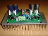
I have changed his schematic to include pairs of output transistors (TO3, NJW0, ...) to support speakers with lower impedance and to include onboard-CAP-multipliers for the frontend voltages.
You need to mount the output transistors, drivers, ... directly onto the heatsink, beneath the PCB (have a look at the image of my prototype).
I will of course send you all a drill-template.
Best regards - Rudi_Ratlos
Attachments
I have revised the layout of the Soft-Power-On PCB.
The schematic now includes a DC-mains - filter behind the Soft-Power-On circuit.
It uses a TAMURA print-transformer that can be wired for 230VAC/50Hz as well as for 115VAC/60Hz mains.
The PCB-size is 95 x 75mm. The price of a PCB incl. the TAMURA-transformer is 10€.
I have ordered 10 PCBs / TAMURA transformers.
Four of them are reserved for GISLE.
If you are interested (Fabian, ROL ?): tell me.
Best regards - Rudi_Ratlos
Attachments

Fabian - the Soft-Power-On PCBs will be green!
Rudi
P.S.: It is not the colour, it is its functionality that makes this PCB so attractive - for the price being offered.
Rudi
P.S.: It is not the colour, it is its functionality that makes this PCB so attractive - for the price being offered.
select a Buffer from this Forum.Is there any circuit diagram for this modification ? I have already read about that solution and it makes sense to me but I would like to know how to apply this precisely. Thanks for the information btw.
Greets,
TrustinTech
B1 and DCB1 can be recommended.
add a vol pot, either 50k or 100k
Use 1uF, or 2u2F, as the input DC blocking cap.
The DCB1 jFETs impose almost no input offset voltage on the vol pot so you don't need a cap after the vol pot.
Read the B1 and DCB1 Threads. But read the other Buffer Threads. There's lots of choice.
You need to mount the output transistors, drivers, ... directly onto the heatsink, beneath the PCB (have a look at the image of my prototype).
I will of course send you all a drill-template.
That heatsink looks quite small... Is it sufficient to dissipate all the heat?
IF heatsink is not an issue, what would be the maximum configurations for the transformer/bias should I aim at? I am not sure if I would go dual-mono config, shipping cost for 2 transformers would be more than themselves...
Thinking of adding the Aikido 12vac buffer just for the sake of having tubes 😱
Gentlemen, I am having big troubles right now!
I wanted to order the parts today, beginning with the NJW0 transistors.
Last week MOUSER had plenty of them on stock.
Today: no stock for the NJW0281G. Availabiliy: May 2015!!
FARNELL does not have either, RSOnline does not have, ...
Does anybody of you know a source for the NJW0281?
I need 72 pcs.
Best regards - Rudi_Ratlos
If someone of you gives me a suitable (and available) alternative for the NJW0 - transistors, I will of course change the layout of the PCB to fit them (if necessary).
I did not order the SYMASYM - PCBs yet.
Best regards - Rudi_Ratlos
I did not order the SYMASYM - PCBs yet.
Best regards - Rudi_Ratlos
Hi Rudi,
just checked the following sources:
digikey 36 x NJW0281G and 176 x NJW0302G
mouser 0 x NJW0281G and 454 x NJW0302G
best regards,
Michael
just checked the following sources:
digikey 36 x NJW0281G and 176 x NJW0302G
mouser 0 x NJW0281G and 454 x NJW0302G
best regards,
Michael
- Home
- Group Buys
- TO-3 SYMASYM