Hey guys!
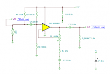
I'm trying to simulate a simple mic preamp with TINA. Here's the circuit I'm using.
So I created a simulation, here it is.
When I run ERC Analysis it's all green. But when I run DC Analysis -> Table of DC Results, I get 2 warnings:
- Pin 1 of Voltage Pin Vout is floating
- Pin 2 of capacitor C3 is floating.
I tried to change that part multiple times but no luck.
Please help me out here.
Thanks!
You need a resistor (say 100k) to ground on the output. The output DC voltage is not defined
unless there is a DC path to ground, or some other node.
unless there is a DC path to ground, or some other node.
Sorry, since I do this the first time - should I add something to the simulation or change the circuit?
I changed the simulation accordingly - added the R5 100k.
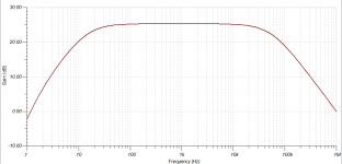
Here's what I get in terms of gain:
Would this be enough to hear a single water drop? I'm not sure.
Here's what I get in terms of gain:
An externally hosted image should be here but it was not working when we last tested it.
Would this be enough to hear a single water drop? I'm not sure.
You'll have to try it, but that's certainly not a loud sound. The mic should be close.
There's something wrong with the gain scale in the graph.
Maybe cutting off the bass (say around 400Hz) will help to reduce noise.
The midband gain of your circuit is around +27dB.
There's something wrong with the gain scale in the graph.
Maybe cutting off the bass (say around 400Hz) will help to reduce noise.
The midband gain of your circuit is around +27dB.
Last edited:
...Here's the circuit I'm using.
- Pin 1 of Voltage Pin Vout is floating
- Pin 2 of capacitor C3 is floating.
That's not the plan in your simulator. And I don't have TINA here to read your TINA file.
But I bet it objects to having one end of a capacitor "floating". SPICE *insists* on figuring the DC voltage on every node before it does any other analysis. But the "floating" end of a cap can float to ANY voltage.
Anyway in real life you would have a LOAD.
Put a reasonable load on that output after the capacitor. Now SPICE's tiny mind will figure the DC voltage here is 0.0000V and be happy.
Attachments
> Would this be enough to hear a single water drop? I'm not sure.
Insufficient information. How much sound power in the drop? How far away? In a room or in the open? What are you going INto? High-gain line input, headphones, mike input?
That's why mike amps have gain controls. In this one, make R4 about 1k. This gives gain of 1 to 100. Most jelly-bean opamps will be clean-enough at gain of 100(*). Set up your system, drip your water, and trim VR1 for happy results.
(*) the slower opamps working at gain of 100 may not have the extended treble to cleanly reproduce, say, Ginger Baker's cymbals. However even the antique '741 opamp at gain of 100 would be flat to 10kHz, which really is all you need in most situations, especially when working very-soft where system and ambient noise intrude.
Let's take SPL 25 dB at the 10 meters distance (32 ').
The idea is to get the input level out of this to connect to a standard line-in.
I tried changing R4 to 1k and then setting VR1 to different levels - it's doesn't change much, still sround -35 dB.
ok, I'll read more about this op amp and see if I can make it better.
Thanks for the hints. I'm still do not understand how this works and I hate this. I'm still reading but I thought I'd make something real.
Let's take SPL 25 dB at the 10 meters distance (32 ').
There's no way this could ever work if you position the mic 32' from the water drop sound
that you want to pick up. The mic would have to be very close.
I looked at your diagram and noticed that you have the value of R2 set at 10k that the diagram shows should be 100k. I corrected that and set the trans-conductance of the controlled current source you used for the electret capsule model to a more reasonable value of 1mS, up from 100uS and got a gain sweep of around 24 dB. The trans-conductance value should be set to match the capsule you end up using.
: still sround -35 dB
The gain should not be *negative* dB!! (That is loss.)
Something is wrong in how you are simulating. With VR1 at 100k and R4 at 1k the gain should be near +40dB.
I hope someone with TINA can read your sim file.
The gain should not be *negative* dB!! (That is loss.)
Something is wrong in how you are simulating. With VR1 at 100k and R4 at 1k the gain should be near +40dB.
I hope someone with TINA can read your sim file.
I simulated it in Tina Pro and get the following.
With 7mV in I get ~ 130mV out.
This is with P1 at max gain.
With 7mV in I get ~ 130mV out.
This is with P1 at max gain.
Attachments
Last edited:
That's close, the gain should be (1 + 100/4.7) = 22.3 times, or 27dB.
You get 130/7 = 18.6 times, or 25.4dB.
You get 130/7 = 18.6 times, or 25.4dB.
That's close, the gain should be (1 + 100/4.7) = 22.3 times, or 27dB.
You get 130/7 = 18.6 times, or 25.4dB.
You are correct - P1 was set at 1% so gain was slightly reduced. Setting it to 0% yields the correct gain.
Attachments
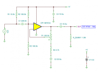
I don't get it... I have almost the same circuit and I get only 13,24uV! Why is that?
Could it be the "electret mic source"?
And yes, the gain < 0...?!
An externally hosted image should be here but it was not working when we last tested it.
Could it be the "electret mic source"?
And yes, the gain < 0...?!
My version of Tina doesn't seem to have the part marked "Pa" (not sure what that is).
But a couple of things - it there power to the opamp? (it doesn't look connected to me, but ERC would test that).
Also - have you tried taking power to your electret module via the 10k resistor?
I'm not entirely sure how that works in simulation.
But a couple of things - it there power to the opamp? (it doesn't look connected to me, but ERC would test that).
Also - have you tried taking power to your electret module via the 10k resistor?
I'm not entirely sure how that works in simulation.
Could it be the "electret mic source"?
Yes, the electret circuit must be wrong. Even if the pot wiper were at the wrong end,
the gain would still be unity.
Yes, the electret circuit must be wrong. Even if the pot wiper were at the wrong end,
the gain would still be unity.
That was my conclusion too.
I don't get it... I have almost the same circuit and I get only 13,24uV! Why is that?..... And yes, the gain < 0...?!
Is it?
Your *assumed* input, divided by output, seems low. By inspection and by Tony's cross-check.
If you assume/hope the capsule works as specified, you do NOT have to simulate that part. What you really want is the AMPLIFIER response. Since lack of output "could be", lack of input, you usually want at least TWO meters on your workbench. Yes, this gets crowded and costly on a bench, but in simulation meters are free and small. LOOK at the input as well as the output. Maybe the VG VCCS pA assembly doesn't really do anything, or not the right thing. Check Everything. On bench I sometimes have 3 meters reading 5 points, and at least as many in sim.
Attachments
- Home
- Design & Build
- Software Tools
- TINA spice simulation gives floating warnings