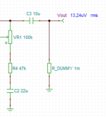
> I get only 13,24uV!
This may actually be the "correct" answer. If the "microphone" sub-unit is not making any output! 13uV/22 is about a half uV, which is the self-hiss of a good opamp.
It would be good to find the "oscilloscope display" in TINA. Then (just as in real life) you would see the "output" is a random jiggle instead of a sine test wave.
SPICE does NOT know your question is. It does NOT know you want "acoustic drip", it is content to tell you "hiss" is valid output.
And it will swallow a more complicated circuit than most humans can. Keep it simple. If you want audio amplifier response, use a simple AC source "equivalent" to your actual source. Yes, the output of a microphone can be 1uV or 1V, but the *gain* should be the same at any input (as long as the output does not clip).
Well, I got the electret capsule from this TI reference design - http://www.ti.com/lit/ug/tidu765/tidu765.pdf. See p.11. Yes, I'm not sure I understand all of that but I'm trying.
On page 13 there's an explanation of "ac transfer characteristic simulation" which I did not get at all.
And I don't know yet what is "preamplifier transfer function". I haven't read anything on op-amps yet.
On page 13 there's an explanation of "ac transfer characteristic simulation" which I did not get at all.
And I don't know yet what is "preamplifier transfer function". I haven't read anything on op-amps yet.
@inkl - I feel you are way over thinking this.
Just build a prototype on breadboard and test it.
The preamp clearly has sufficient gain, assuming an electret mic output of ~7mV or so.
Just build a prototype on breadboard and test it.
The preamp clearly has sufficient gain, assuming an electret mic output of ~7mV or so.
I do want to build a prototype, actually multiple. But I also want to understand at least the basics.
Also, I find these simulations the best way to find out which circuit suits the needs.
Also, I find these simulations the best way to find out which circuit suits the needs.
Have a look at this study below to get an idea of the sound levels produced by drops of water at a certain distance from the microphone. It may help you to establish the sensitivity required of your microphone and op-amp amplification needed.Once you know this you may be able to plug the values into the TI model and determine the correct operation and SNR.
(PDF) Sound Wave Energy Resulting from the Impact of Water Drops on the Soil Surface
(PDF) Sound Wave Energy Resulting from the Impact of Water Drops on the Soil Surface
Looking at inkl's circuit diagram in post number 16, what is the value of R_DUMMY supposed to be? I presume that inkl intends it to be 1 Megohm, but in LTspice at least (I'm not familiar with Tina) a resistor with a value of 1m has a resistance of 1 milliohm. In LTspice to give a resistor the value of 1 Megohm it needs to be 1Meg, not 1m.
If I'm correct, and R_DUMMY has been given a value of only 1 milliohm, then the output is effectively shorted to ground, and this would explain the very low output showing in inkl's simulation.
If I'm correct, and R_DUMMY has been given a value of only 1 milliohm, then the output is effectively shorted to ground, and this would explain the very low output showing in inkl's simulation.
Looking at inkl's circuit diagram in post number 16, what is the value of R_DUMMY supposed to be? I presume that inkl intends it to be 1 Megohm, but in LTspice at least (I'm not familiar with Tina) a resistor with a value of 1m has a resistance of 1 milliohm. In LTspice to give a resistor the value of 1 Megohm it needs to be 1Meg, not 1m.
If I'm correct, and R_DUMMY has been given a value of only 1 milliohm, then the output is effectively shorted to ground, and this would explain the very low output showing in inkl's simulation.
In my version of Tina, 1m is indeed 1 milliohm and 1M is 1 megohm.
Good spot!
Have a look at this study below to get an idea of the sound levels produced by drops of water at a certain distance from the microphone. It may help you to establish the sensitivity required of your microphone and op-amp amplification needed.Once you know this you may be able to plug the values into the TI model and determine the correct operation and SNR.
(PDF) Sound Wave Energy Resulting from the Impact of Water Drops on the Soil Surface
Thank you. Very good read.
Looking at inkl's circuit diagram in post number 16, what is the value of R_DUMMY supposed to be? I presume that inkl intends it to be 1 Megohm, but in LTspice at least (I'm not familiar with Tina) a resistor with a value of 1m has a resistance of 1 milliohm. In LTspice to give a resistor the value of 1 Megohm it needs to be 1Meg, not 1m.
If I'm correct, and R_DUMMY has been given a value of only 1 milliohm, then the output is effectively shorted to ground, and this would explain the very low output showing in inkl's simulation.
I used 100k.
In my version of Tina, 1m is indeed 1 milliohm and 1M is 1 megohm.
Good spot!
😱 Really?! Good catch!
I used 100k.
In post #16 you have 1m (milliohm) ?
Attachments
In post #16 you have 1m (milliohm) ?
Yes, but I used both values.
> I get only 13,24uV!
And it will swallow a more complicated circuit than most humans can. Keep it simple. If you want audio amplifier response, use a simple AC source "equivalent" to your actual source. Yes, the output of a microphone can be 1uV or 1V, but the *gain* should be the same at any input (as long as the output does not clip).
ok, I changed it to a simple AC sine source:
An externally hosted image should be here but it was not working when we last tested it.
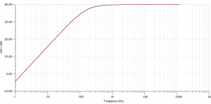
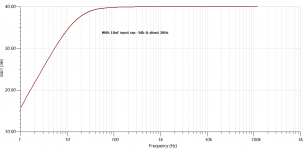
That AC setting in TINA is kind of misleading, so I guess I set it right. And the gain now (with VR1 set to 1%):
An externally hosted image should be here but it was not working when we last tested it.
Which is just weird to me...
With the simple voltage source as shown in post #33 you do not need R1, so get rid of it for the simulation.
Other than that, why does the gain plot appear weird to you? Looks good to me.
The response of the circuit is -3dB at 14.5 Hz. Your plot is 0.1dB down at 100 Hz, which seems about right to me.
Note that your y axis (vertical) has a very compressed range of just 0.1dB. If you widen the frequency range and plot from (say) 1Hz to 1MHz this will sort itself out and the plot will look more normal.
Which is just weird to me...
Other than that, why does the gain plot appear weird to you? Looks good to me.
The response of the circuit is -3dB at 14.5 Hz. Your plot is 0.1dB down at 100 Hz, which seems about right to me.
Note that your y axis (vertical) has a very compressed range of just 0.1dB. If you widen the frequency range and plot from (say) 1Hz to 1MHz this will sort itself out and the plot will look more normal.
Oh, yes, R1 is removed as we don't need to supply any voltage to JFET in the mic (as far as I understand).
Thank you for the gain explanation. Well, 25dB is simply too low. I'll try to simulate other circuit today.
Thank you for the gain explanation. Well, 25dB is simply too low. I'll try to simulate other circuit today.


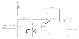
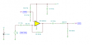
I added C2 and C3 by analogy to previous circuit. Not sure they're needed but I think this is a DC offset filters and they won't hurt... I guess.
I think you have an error in your schematic.
Originally I did not have one. But the gain curve is still the same. Could you please explain why it's not needed here?
Originally I did not have one. But the gain curve is still the same. Could you please explain why it's not needed here?
When running an OPAMP off a single supply you need to set a mid point reference for one of the inputs.
This is what R1 / R2 are doing (ref my diagram)
I would also say the input cap needs to be larger.
Attachments

Last edited:
- Home
- Design & Build
- Software Tools
- TINA spice simulation gives floating warnings