TIM reduction for treble drivers/tweeters
In the old days before T/S parameters - in this particular instance that means 1977, we had a loudspeaker guru here in Denmark with the name of Peter Holm. I don’t exactly know his background, but it was academic with a lot of practical experience. He was somehow connected with the distributor of Goodmans speakers out of the UK.
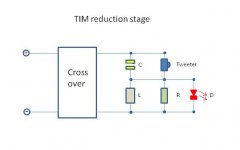
He designed a TIM reduction stage for treble drivers, because TIM distortion with frequencies above 20 KHz needs somewhere to go, not to distort the area below 20 KHz, and not to be converted into heat in the treble driver voice coil eventually killing it.
It all seems very plausible, and it is actually just another 6 dB ´way´ in a traditional filter, and can be used both in parallel and serial filters, and it only needs 3 components - 4 if you want a visual indicator.
Hopefully the picture is attached.
And here are the formulas:
f the attack frequency of the filter, down 3 dB
R the nominal impedance of the treble driver
C 160,000/(f x R) in uF
L (160 x R)/f in mH
D standard LED (optional)
Example, 8 ohm driver, and 20 KHz:
R = 8 ohm power resistor, probably 5 – 10w will do
C = 160,000/(20,000 x 8) = 1 uF, plastic crossover cap
L = (160 x8)/20,000 = 0.06 mH coil
If you can’t get the coil in the right value just buy the closest one larger, and hook it up to a inductance meter and unwind straighten out and measure until the value is right, then cut the excess wire.
All that said I have also had very good experience in reducing aggressive tendencies in the upper mids (typically 400 – 1200Hz) in HiFi speakers by using a standard treble driver resonance reduction filter – try it!
Best regards
Arthur.
In the old days before T/S parameters - in this particular instance that means 1977, we had a loudspeaker guru here in Denmark with the name of Peter Holm. I don’t exactly know his background, but it was academic with a lot of practical experience. He was somehow connected with the distributor of Goodmans speakers out of the UK.
He designed a TIM reduction stage for treble drivers, because TIM distortion with frequencies above 20 KHz needs somewhere to go, not to distort the area below 20 KHz, and not to be converted into heat in the treble driver voice coil eventually killing it.
It all seems very plausible, and it is actually just another 6 dB ´way´ in a traditional filter, and can be used both in parallel and serial filters, and it only needs 3 components - 4 if you want a visual indicator.
Hopefully the picture is attached.
And here are the formulas:
f the attack frequency of the filter, down 3 dB
R the nominal impedance of the treble driver
C 160,000/(f x R) in uF
L (160 x R)/f in mH
D standard LED (optional)
Example, 8 ohm driver, and 20 KHz:
R = 8 ohm power resistor, probably 5 – 10w will do
C = 160,000/(20,000 x 8) = 1 uF, plastic crossover cap
L = (160 x8)/20,000 = 0.06 mH coil
If you can’t get the coil in the right value just buy the closest one larger, and hook it up to a inductance meter and unwind straighten out and measure until the value is right, then cut the excess wire.
All that said I have also had very good experience in reducing aggressive tendencies in the upper mids (typically 400 – 1200Hz) in HiFi speakers by using a standard treble driver resonance reduction filter – try it!
Best regards
Arthur.
Attachments
Last edited:
A diode will cut off the amplitude above the forward voltage which means you get a square (halve-) wave. That adds distortion instead reducing it.
The optional LED is odd. But otherwise looks like a resonance trap. Worth a look in a simulation, at least.
Yes the diode will rectify the signal above 20KHz, but do you think it will affect the signal that comes out of the speakers?
I have used the circuit years ago, but that were without the diode.
At the moment I am working on a Leslie project, and Leslies are known for killing their treble drivers.
Then there is no need to pass frequencies above 6 KHz to make it happen earlier.
I have used the circuit years ago, but that were without the diode.
At the moment I am working on a Leslie project, and Leslies are known for killing their treble drivers.
Then there is no need to pass frequencies above 6 KHz to make it happen earlier.
Yes the diode will rectify the signal above 20KHz, but do you think it will affect the signal that comes out of the speakers?
Yes, it will because it interacts with the impedance and the amplifier. The C/L pulls the impedance quite low too btw. Not every amp works great with something like this, some will start to oscillate others will behave quite odd, i.e. class D amps don't like fluctuating impedances, esp. in the treble, it interacts with the output inductance/filter.
Buf if you don't think it will affect the signal, why bother with it anyway?
Then there is no need to pass frequencies above 6 KHz to make it happen earlier.
Well, if you want to reduce the TIM, use better drivers, reduce the interaction between speaker/crossover, use higher xo frequencies, modify drivers (damping the pole core i.e.), use a (different?) horn/waveguide or use a limiter to prevent clipping, because that's the only way dangerous harmoics would harm the tweeter. Everything else is just a matter of power or xo-frequency.
In HiFi applications you won't reduce the TIM between 400 and 1200Hz that way because the tweeter doesn't work in that range anyway.
Sorry I didnt explain the circuit well enough.
The schematic shows a 2 way 6 db/oct. serial filter where the tweeter gets all the frequencies up to 20 KHz, and R (the super tweeter if you will) gets all the frequences above 20 KHz.
The reason is that the TIM has to be burned off somewhere (in R).
Why a diode - because you would maybe want a visual indication if some TIM actually is burned in R.
The 400 -1200 Hz subject is a whole different story - a resonance reduction circuit that you can find in all good loudspeaker literature. Used to reduce the resonance peak in tweeters. It has nothing to do with the TIM circuit.
The TIM could be generated in the amps etc. so better speakers would not help.
Hope that make things more clear.
The reason is that the TIM has to be burned off somewhere (in R).
No, that's completely wrong. If it's not produced in the tweeter, fix your signal chain. If it is produced in the tweeter, it will be radiated from the tweeter because it's already in the mechanical system. You can't just shave off the TIM and put it somewhere else.
Why a diode - because you would maybe want a visual indication if some TIM actually is burned in R.
That's something you got completely wrong too. You can hear it way before the LED becomes lit. And the LED makes it worse, not better in any way.
The 400 -1200 Hz subject is a whole different story - a resonance reduction circuit that you can find in all good loudspeaker literature. Used to reduce the resonance peak in tweeters. It has nothing to do with the TIM circuit.
You can ofcourse use a filter to filter peaks and you can use filters to eliminate impedance peaks. But it's not a 'TIM-Filter', it's an equalizing filter which reduces the sound level and the distortion at the same time with the exact same ammount. You simply can't filter out TIM separately.
The TIM could be generated in the amps etc. so better speakers would not help.
Sorry, but that's completely wrong. Again: You simply can't filter out TIM separately, if it's generated in the amp, you have to fight it there. You can't get the eggs out of the cake, you'll never get them back as they were, it's exactly the same. And better speaker (and/or xo) will ofcourse help, if the reason is too low rating, too low impedance or simply too much distortion from one or more drivers. Even higher efficiency drivers can help because they need less power.
According to this site, "[FONT=Arial, Arial, Helvetica]The stock Leslie high-frequency driver is pretty fragile, and is easily overloaded with a stock 40-watt amplifier."At the moment I am working on a Leslie project, and Leslies are known for killing their treble drivers.
"Unearthing The Mysteries of the Leslie Cabinet"
[/FONT]
benb,
yes and that is why I thought it would be a good idea to filter out all frequencies that are not needed, because they will still heat up the voice coil. In the Leslie instance that would be around 5 - 6 KHz.
Newer drivers have a larger frequency span, which makes them harsh in a Leslie. I think this filter will take care of that too.
ICG,
let us just agree that we dont agree in anything.
I have been building and modifing speakers all my life, with excellent results.
-------------------------------------------------------------------------------------
Serial filters seem to be an almost lost art, so here is how they work.
I suppose this will further clarify my intentions with this filter - to bypass anything above 20 KHz from the tweeter.
Best regards
Arthur.
Attachments
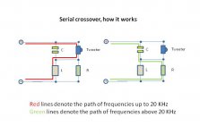
This is a normal HP and a LP filter, just with a resistor to consume the energy.
Peter Holms theory were that if you dont consume the energy it will go somewhere else.
Peter Holms theory were that if you dont consume the energy it will go somewhere else.
Hi,
This is just very poor theory masquerading as knowledge.
Organ amplifiers are a classic tweeter fryer due to simple
amplifier clipping on sustained notes, and the circuit will
not do a great deal to alleviate the basic problem.
The circuit is pretty harmless, and probably inaudible to
anyone over say 40. Its just a crude 1st order filter at
20KHz, a simple series inductor would do the same job.
(A parallel 50R resistor before the inductor is an idea.)
It is of course a nonsense the energy has to go somewhere.
For the series inductor it simply doesn't get out of the amplifier.
rgds, sreten.
Last edited:
That is your opinion.
In an organ an overdriven amp will deliver a lot of energy above 5 - 6 KHz, where I would put the corner freq. in this application.
This energy would be converted to heat in the treble driver - where else should it go?
Eventually killing it.
In an organ an overdriven amp will deliver a lot of energy above 5 - 6 KHz, where I would put the corner freq. in this application.
This energy would be converted to heat in the treble driver - where else should it go?
Eventually killing it.
This energy would be converted to heat in the treble driver - where else should it go?
In the case of a simple series inductor between tweeter crossover and tweeter it will simply not be generated from the beginning ! Simple as that.
I don't beleive in the TIM reduction thingie either. In the case of TIM damage is already done and it can't be undone by simply cutting off sound that is not perceivable. But you will introduce a further unnecessary response error with this cuircuit.
If there is one place where a lowpass can reduce TIM then it is at the input of a power amp. But as long as an amplifier's slew rate is high enough, TIM shouldn't be of concern.
Regards
Charles
This is just very poor theory masquerading as knowledge.
Organ amplifiers are a classic tweeter fryer due to simple
amplifier clipping on sustained notes, and the circuit will
not do a great deal to alleviate the basic problem.
That's exactly the point. To use a limiter, filter in the amp or a higher rated tweeter will help.
The circuit is pretty harmless, and probably inaudible to
anyone over say 40. Its just a crude 1st order filter at
20KHz, a simple series inductor would do the same job.
(A parallel 50R resistor before the inductor is an idea.)
I'd prefer to put the filter into the amp, but it would be easier and more effective either way.
It is of course a nonsense the energy has to go somewhere.
For the series inductor it simply doesn't get out of the amplifier.
Exactly!
ICG,
let us just agree that we dont agree in anything.
[...]
That is your opinion.
There isn't anything to agree with, that's physics. And physics got a great thing in it, it's true wether you believe in it or not.
I have been building and modifing speakers all my life, with excellent results.
See, that's the thing. Exactly the thing. You can do something your whole life and still do it wrong. You can build things that's great if you put enough effort in try and error combined with a few fragments of knowledge but you can do it a lot better and way faster if you understand how it fundamentally works.
Serial filters seem to be an almost lost art, so here is how they work.
I suppose this will further clarify my intentions with this filter - to bypass anything above 20 KHz from the tweeter.
You automatically assume because noone agrees with you they don't understand it. That's not the case, it's the opposite, you don't even think about someone else might be right. For a serial crossover you have to match much more circumstances, they have a lot of disadvantages. You have almost always to flatten the impedance for ideal results and tolerances in the components are much more critical because they apply always to both ways. And that's not only the L and C, it's also the driver itself. That means, the impedance has to be the same on the LF and HF transducer has to be the same impedance, you can't mix 8 and 4 Ohm i.e.. Different isn't better just because it's different, a serial crossover takes a lot more time to develop properly and often doesn't work as well as a parallel crossover.
so its a series crossover with the tweeter in the woofer leg and resistor load in the tweeter leg. Would 1uF/0.06mH be good starting values for nominal 8 ohm tweeters?
Hi Freddi,
yes that is exactly what it is - no rocket science, and easy to understand, for most of us 🙂
The values is a good starting point.
My intend is to offload a Leslie driver @ around 5 - 6 KHz, and to soften the distortion sound, because the new drivers have a wider frequency span, but the original intend were to use it in HiFi speakers.
- Status
- Not open for further replies.
- Home
- Loudspeakers
- Multi-Way
- TIM reduction for tweeters