
This schematic is like the weather, changeable. I'll stuff this version into the simulation. But I think it doesn't have the ability to drive the 6080. There is not enough B+ to satisfy two triodes in series & still get the ~155V p-p.
And this version has far too much gain. That is why I went with a first stage ECC81 to try for something more normal. Many amps are designed for full output with a One volt signal.🙂
And this version has far too much gain. That is why I went with a first stage ECC81 to try for something more normal. Many amps are designed for full output with a One volt signal.🙂
cascodes can not drive power tubes with gusto, it needed a buffer, tube of mosfet, you choose...
I think the OP's plan to convert to SRPP is a good one, but there's an issue around V3. We don't know what yet.
Maybe a final version could have the first stage ECC83 running wide open, maybe with the cathode degenerated, and loop feedback brought to the cathode of V2? Output valve's grid resistor to ground, keep the 5pF for auld lang zine. Feedback polarity needs inverting, of course.
YOS,
Chris
Maybe a final version could have the first stage ECC83 running wide open, maybe with the cathode degenerated, and loop feedback brought to the cathode of V2? Output valve's grid resistor to ground, keep the 5pF for auld lang zine. Feedback polarity needs inverting, of course.
YOS,
Chris
a 6072 stacked like the input stage of an Aikido, or better yet an Aikido drive will be very good way imho...b+ to 350 volts.....
6072 and 5687 combo....
6072 and 5687 combo....
This schematic is like the weather, changeable. I'll stuff this version into the simulation. But I think it doesn't have the ability to drive the 6080. There is not enough B+ to satisfy two triodes in series & still get the ~155V p-p.
And this version has far too much gain.
I was quite impressed by the 83 88 circuit, it had a huge voltage swing and was very linear, and a gain of 1000. With feedback(s) the overall gain reduced by 14dB. I don't know if you believe in magic, but I have seen that number before.... Also remember the original circuit implies the amp was designed as an integrated.
cascodes can not drive power tubes with gusto
Indeed.
Your schematic in post #8 shows a voltage divider of about 3:1 between V3's anode and the bottom of its cathode resistor, feeding G1. That's a little more than +20 volts between G1 and the bottom of the cathode resistor. You can see how somebody on this thread would become worried that we're not seeing a true schematic. Now I'm expecting another surprise like triangle waves.
ho ho. Remember that V3 is the one conducting all the current. Both of the 820Rs in the SRPP have 4 volts across them, as you would expect. I wasn't really thinking too hard when I did the pull up, I tried it and it worked, 750k was more of an aesthetic choice, as there was one on the circuit already in about the right place 🙂.
I was interested to see in my scope plot earlier, it does seem to be able to pull up higher than the steady state voltage rail as well, a little perplexing, I will check my scope probe, but I am pretty sure it is OK.
Isn't the recommended Pete Millet mosfet source follower pcb for push-pull?
Using it doesn't make sense.
Seems too many strange ideas, like the above and the SRPP suggestion, are being presented.
TdeP did know a thing or two.
t
Using it doesn't make sense.
Seems too many strange ideas, like the above and the SRPP suggestion, are being presented.
TdeP did know a thing or two.
t
Nobody's talking about pcb's. The OP found that the original design was inadequate, and folks are suggesting fixes to an existing, working OK but not optimal, amplifier. I think we could all agree that the original design was poorly thought out.
Trying to drive a mu of 2 output valve from the same power supply voltage as the final is just going to be a rough row to hoe. The driver will need to be optimized for output swing, and the TdP original isn't quite.
YOS,
Chris
Trying to drive a mu of 2 output valve from the same power supply voltage as the final is just going to be a rough row to hoe. The driver will need to be optimized for output swing, and the TdP original isn't quite.
YOS,
Chris
Isn't the recommended Pete Millet mosfet source follower pcb for push-pull?
Using it doesn't make sense.
Seems too many strange ideas, like the above and the SRPP suggestion, are being presented.
TdeP did know a thing or two.
t
yes, but no reason not to be able to use that for this project...
TimDeP would surely run a tantrum if he reads our comments..... 😀
but we are here to look at all possible solutions...
while i like cascodes on solid state amps like the super leach, and the pioneer spec 2 i have yet to see its merit with tubes....
Last edited:
Nobody's talking about pcb's.
Read Tony Tecson's posts 43 and 51--he does so.
Using a PP pcb for SE doesn't make a lot of sense but as he days it is doable
Read Tony Tecson's posts 43 and 51--he does so.
Using a PP pcb for SE doesn't make a lot of sense but as he days it is doable
cascodes can not drive power tubes with gusto
Cascodes are certainly reknown for their high output impedance but doesn't the local feedback of R13 negate a lot of that?
Cascodes are certainly reknown for their high output impedance but doesn't the local feedback of R13 negate a lot of that?
The OP found that the original design was inadequate
I'm not sure which design the OP built as the designs he presents in posts 4 and 8 are NOT the TdeP design.
It seems that the sims being presented are not of the correct design.
Yje correct/original design is in post 42.
I'm not sure which design the OP built as the designs he presents in posts 4 and 8 are NOT the TdeP design.
It seems that the sims being presented are not of the correct design.
Yje correct/original design is in post 42.
The design in #42 has far too much gain, do the numbers, don't even need a 4-function calculator. The output impedance of a cascode is essentially same as a pentode, dominated by Rl. the load resistor. Parallel that with the following Rg & the very high R of the Cascode, you have the answer.🙂
TdeP suggested that the trick to use the 6080 in SE was for it to swing 200V peak to peak into it to get enough drive.
The amp has/had a sensitivity of around 200mV (for full output)---it is an integrated amp not a power amp.
Local feedback (R13) is used to get enough bandwidth from the driver stage and to keep it linear over its wide operating range.
Bandwidth was/is said to be very good and was something like 10Hz to 60Hz (-1dB).
TdeP might have been difficult at times but he was a competent designer.
The OP found that the original design was inadequate
I'm not sure which design the OP built as the designs he presents in posts 4 and 8 are NOT the TdeP design.
It seems that the sims being presented are not of the correct design.
Yje correct/original design is in post 42.
Hi, I originally built a copy of the circuit in #42, and the static values were in the ball park of the values on the circuit. My HT was 10 volts higher. I found the amp struggled with asymmetrical slewing, and also would have needed carefully selected ECC88s for symmetry at the cascodes output, a feature shared with the 859's cascode incidentally, but in that case required to set the output tubes bias current, subsequently improved on the 869. So after a bit of playing around I ended up with the circuit in #8, and it now works very nicely, and is a good amp imo.
TdeP suggested that the trick to use the 6080 in SE was for it to swing 200V peak to peak into it to get enough drive.
The amp has/had a sensitivity of around 200mV (for full output)---it is an integrated amp not a power amp.
Local feedback (R13) is used to get enough bandwidth from the driver stage and to keep it linear over its wide operating range.
Bandwidth was/is said to be very good and was something like 10Hz to 60Hz (-1dB).
TdeP might have been difficult at times but he was a competent designer.
Mine still struggles with HF, but can now get to 20k sine with symmetrical slewing. I have a lot of respect for Tim, young me worked for him in the mid 90's. He did like to keep things close to his chest, but I learn a lot, and maybe worked out a few of the little tricks for myself.....
TdeP suggested that the trick to use the 6080 in SE was for it to swing 200V peak to peak into it to get enough drive.
The amp has/had a sensitivity of around 200mV (for full output)---it is an integrated amp not a power amp.
Local feedback (R13) is used to get enough bandwidth from the driver stage and to keep it linear over its wide operating range.
Bandwidth was/is said to be very good and was something like 10Hz to 60Hz (-1dB).
TdeP might have been difficult at times but he was a competent designer.
With 70V on the cathode 200V p-p is terrible grid clipping. Something a serious guitar picker might do to enhance the performance. 140V p-p gets full drive in Class A.
BW will be determined by the OPT more than any other factor. No point in a driver with response from DC to green light, doesn't matter.🙂
Good design does not need hand selected components every time.😱
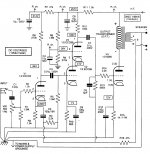
I did sim the original TdeP cicuit from post #42.
The total open loop gain (w/o both FBs) is 63dB which drops to 30dB with FBs applied, so about 33dB GNFB. No surprise as both the ECC83 and the cascode have high gain.
And yes, sensitivity is around 0.2 Volts. THD at 2W into resistive load about 3%, 2nd harmonic 10x higher than all the rest. Output impedance about 1 ohm.
The interesting things happen when the local FB is removed, R13 connected to GND.
This does not change the overall gain too much, just a little, +3 dB maybe.
But both, THD and output impedance, drop to 1/10 their previous numbers, THD is now down to below 0.2% (from 3%), output impedance now down to about 0.1 ohm (from 1 ohm), at the same 2W output into resistive load. And the sonic signature has lost its predominant 2nd which is still bigger than 3rd but not by much.
It seems that the FB through R13 reverses some of the effects of the huge GNFB and makes the amp appear more "tubey" ...
By the way, in my sim the output of the cascode was also a little low and produced early clipping which could be corrected by lowering the 100k load R10. And the cascode is quite sensitive to tube parameters, using slightly different tube models moves its output up and down +/- 20 volts easily.
- Home
- Amplifiers
- Tubes / Valves
- Tim De Paravicini's HiFi World 6080 amp modded by me.