i question the use of 63 db open loop gain and global feedback on a power tube that has very low rp to begin with, why?
why not ditch the global feedback and just settle for an overall gain of lower than 30db?
no one is questioning the competence of TimdeP, it is just that different strokes for different folks are prevalent with diy'ers....
we do not worship a cult of originality for originality's sake...we do not grow if we did...
cascodes can not drive power tubes with gusto
Cascodes are certainly reknown for their high output impedance but doesn't the local feedback of R13 negate a lot of that?
yes and to drive a power output grid directly is iffy....a buffer surely helps....
I did sim the original TdeP cicuit from post #42.
Can you post that sim please, your results don't make sense.
Can you post that sim please, your results don't make sense.
I did sim the original TdeP cicuit from post #42.
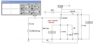
The total open loop gain (w/o both FBs) is 63dB which drops to 30dB with FBs applied, so about 33dB GNFB. No surprise as both the ECC83 and the cascode have high gain.
And yes, sensitivity is around 0.2 Volts. THD at 2W into resistive load about 3%, 2nd harmonic 10x higher than all the rest. Output impedance about 1 ohm.
The interesting things happen when the local FB is removed, R13 connected to GND.
This does not change the overall gain too much, just a little, +3 dB maybe.
But both, THD and output impedance, drop to 1/10 their previous numbers, THD is now down to below 0.2% (from 3%), output impedance now down to about 0.1 ohm (from 1 ohm), at the same 2W output into resistive load. And the sonic signature has lost its predominant 2nd which is still bigger than 3rd but not by much.
It seems that the FB through R13 reverses some of the effects of the huge GNFB and makes the amp appear more "tubey" ...
By the way, in my sim the output of the cascode was also a little low and produced early clipping which could be corrected by lowering the 100k load R10. And the cascode is quite sensitive to tube parameters, using slightly different tube models moves its output up and down +/- 20 volts easily.
Interesting results, I measured the THD but I am not really set up properly at the moment, my recently acquired 8903b has no 400Hz filter, annoying, and I haven't sorted out an attenuator to go in to sound card yet. but on the sound card at fairly low power I did notice (this is on my mod circuit #8) that the 2nd harmonic is dominant and all others are much lower value. Next time I have it on the bench I will investigate a switch for the R13.
Agreed about ECC88 tube parameters as well. The SRPP seems much more accommodating. You don't mention slewing, did your simulation have any thoughts on that?
I did sim the original TdeP cicuit from post #42.
Can you post that sim please, your results don't make sense.
why not ? after all the R13 FB is positive FB, sort of ...
it is not a bootstrap though as it does not boost the cascode's load
say we inject a positive signal spike through the normal GNFB point into the cathode of the input triode, it is inverted only once in the cascode before it reaches the grid of output V4, as V1 is in grounded grid mode for the FB and does not invert;
the same positive spike on the FB line however gets to the grid of output V4 as is, no inversion;
if the GNFB is polarised correctly as negative FB, then R13 FB must be positive FB ...
the only open question to me is, why does it have such a big impact, as it has to pass through 680kohm and work against the output impedance of the driver; but on the other hand, the cascode is high impedance, almost 100kohm ...
here you go, LTSpice schem + tube models, zipped
Attachments
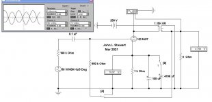
Who Said Drive The 6080 With 200V p-p
Pls step forward. How do you think this would 'sound'?
One sim shews steady state at no signal, the other bias shift & terrible waveform.
I get the sense that people are simply throwing darts at the problem. Not much thought, just hope it works. That is not how real development is done.🙄
Pls step forward. How do you think this would 'sound'?
One sim shews steady state at no signal, the other bias shift & terrible waveform.
I get the sense that people are simply throwing darts at the problem. Not much thought, just hope it works. That is not how real development is done.🙄
Attachments
why not ? after all the R13 FB is positive FB, sort of ...
it is not a bootstrap though as it does not boost the cascode's load
say we inject a positive signal spike through the normal GNFB point into the cathode of the input triode, it is inverted only once in the cascode before it reaches the grid of output V4, as V1 is in grounded grid mode for the FB and does not invert;
the same positive spike on the FB line however gets to the grid of output V4 as is, no inversion;
if the GNFB is polarised correctly as negative FB, then R13 FB must be positive FB ...
the only open question to me is, why does it have such a big impact, as it has to pass through 680kohm and work against the output impedance of the driver; but on the other hand, the cascode is high impedance, almost 100kohm ...
here you go, LTSpice schem + tube models, zipped
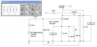
Thanks for this, I find it comforting that the problems I encountered in real life are present in the sim. Unfortunately the sim also has
my version down 13dB at 20kHz, where as the original is only 10dBs down...... I can assure you much better in reality!
Also confession time, on my circuit in #8 the left hand R9 should be 27k, not 270k, well spotted, and sorry, seems I am getting a bit rusty with my colour codes, as my eyesight slowly deteriorates.
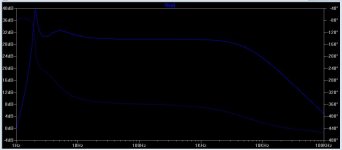
Simulation FR of the original.
Both feedbacks are negative. the 6080 grid is in phase with the output.
Attachments
Last edited:
...the sim also has my version down 13dB at 20kHz, where as the original is only 10dBs down...... I can assure you much better in reality!
... the 6080 grid is in phase with the output.
true, 6080 grid is in phase with output ... and what happens if you *add* some of the output signal by means of R13 ? isn't negative FB when you *subtract* a fraction of the output signal ... ?
as for frequency response in sim the problem is that in spice the transformer model is an ideal with constant inductance over frequency range; whereas in reality inductance is high at LF and drops significantly with rising frequency; say 10H @ 50Hz / 1H @ 5kHz / 100mH @ 50kHz; so you can't sim both ends correctly at the same time with the simple model - put in 10H for the primary and get an idea of the LF response (and ignore the HF end) - or drop prim and sec inductance to 1/10 and look at the HF response (and ignore the LF end); the coupling factor (I used 0.995) also affects the HF as it represents leakage inductance; try 1 for a change ...
by the way, forgot to include the 6080 model for the sim, attached
Attachments
... on my circuit in #8 the left hand R9 should be 27k, not 270k ...
and that closes the case about whether V3 is in grid current; with 270k the grid would definitely draw current and V3 pulls the cascode output way up; not so with 27k ...
concerning R13 FB what seems to happen is this:
global nFB does a pretty good job to correcting for the non-linearities of the 6080 because of high open loop gain; to accomplish this it has to pre-distort the 6080's grid signal;
this can be seen: the closer the amp gets to max output the more crooked the grid signal becomes while the output is still almost clean;
now R13 adds a fraction of the almost clean output to the deliberately pre-distorted grid drive, attempting to straighten it, which in turn makes the output less clean ...
that might explain why distortion and output impedance go up when R13 is connected as FB rather than with GND ...
Last edited:
When describing a circuit's performance, feedback, etc. . . .
Please start with:
1. You are talking about the original Cascode driver stage.
or
2. You are talking about the SRPP driver stage.
or
3. Tell which Post # schematic you are talking about.
And, with those two different driver stages, the resistor numbers change.
And by the way, when modifying that amplifier from Cascode to SRPP, it only takes one mistake in the conversion process, to make the driver stage Neither Cascode, Nor SRPP.
With such a mistake, all descriptions and theory of the performance are meaningless.
Last edited:
Since this issue of positive feedback seems to creep back into the discussion, let's define how much there actually is, in any of the proposed versions. Signal from the 8 Ohm output tap is attentuated by a factor of 52.8 at the "bottom" of R13 + 5pF. In the TdP version with cascode driver this is further attenuated by a factor of (minmum) 6.8 to the output valve's G1, for a total of 359. (In SRPP, that number is even higher.)
Supposing that the amplifier could make 5 Volts output into load, that's .014 Volts feedback at a grid with 50 Volts signal. So, there's no significant positive feedback. Effects seen are as the OP says, all from negative feedback to the first valve's cathode.
I've personally softened about this design through this discussion - yeah, it doesn't quite get to full clipping in the output stage, like we all expect these days - but I predict some design elements will become more common in future DIY projects. The best solid state designs don't clip the output stages, and that's considered modern Cordell-level design.
YOS,
Chris
Output Stage FB
About 0.11 db +ve. I assumed the signal source to be 100K, the combination of the load Rl in parallel with the cascode driver plate resistance.
Somewhere in my pile I still have the negatives of traces taken around 1060 of a real cascode on the bench taken with a TEK scope camera on a TEK 540 Series scope. I'll have a look, who knows might even find them!😀
Attachments

Since this issue of positive feedback seems to creep back into the discussion, let's define how much there actually is, in any of the proposed versions. Signal from the 8 Ohm output tap is attentuated by a factor of 52.8 at the "bottom" of R13 + 5pF. In the TdP version with cascode driver this is further attenuated by a factor of (minmum) 6.8 to the output valve's G1, for a total of 359. (In SRPP, that number is even higher.)
Supposing that the amplifier could make 5 Volts output into load, that's .014 Volts feedback at a grid with 50 Volts signal. So, there's no significant positive feedback. Effects seen are as the OP says, all from negative feedback to the first valve's cathode.
I've personally softened about this design through this discussion - yeah, it doesn't quite get to full clipping in the output stage, like we all expect these days - but I predict some design elements will become more common in future DIY projects. The best solid state designs don't clip the output stages, and that's considered modern Cordell-level design.
YOS,
Chris
There is no positive feedback , just somebody didn't followed the schematic ...
If it is useful to have negative feedback in the grid of the 6080 and why is a good question , probably Tim de Paravicini knew exactly what he was doing 😀
Last edited:
There is a minute +ve FB in all the schematics so far. Perhaps Tim DeP knew what he was doing but the records of such are a mess. What was his background, can we find any other samples of his work? If people are prolific there is usually plenty of evidence.🙂
as for frequency response in sim the problem is that in spice the transformer model is an ideal with constant inductance over frequency range; whereas in reality inductance is high at LF and drops significantly with rising frequency; say 10H @ 50Hz / 1H @ 5kHz / 100mH @ 50kHz; so you can't sim both ends correctly at the same time with the simple model - put in 10H for the primary and get an idea of the LF response (and ignore the HF end) - or drop prim and sec inductance to 1/10 and look at the HF response (and ignore the LF end); the coupling factor (I used 0.995) also affects the HF as it represents leakage inductance; try 1 for a change ...
Thanks for the spice transformer info. I don't understand why it works, but it does. Bit of work for me to fathom that one.
This is interesting in this case, the #42 circuit is flat out to 24 kHz and dp's honor is upheld. The 5pf slows the drive down, and in the simulation the effect is the 6080's grid drive making it slower but symmetrical. Interesting.
I feel a slight pressure to put it back to the original circuit now. But I won't (probably), I quite like it as it is, and the SRPP enabled me to take out 2 large caps, and have better PSRR, so it would be a bit of an upheaval....
But 0.05% distortion (680k to ground)........ I wonder what that would sound like....
Oh, that Tim is still tormenting me.
Probably oscillate....
Tim de P References
He seems to be in systems as well as various components. I do recall references to Tim, Patrick Turner did not think well of Tim's amplifiers.
Reading their descriptions sounds more like brute force than any kind of finesse such as the McIntosh. Digging a little farther I found a couple of 6AS7/6080 SE amps in historic DIY posts. But none like this one.
In its present form this SE amp is a Dog.🙁
Tim & his various projects appeard in magazines published to sell his & other similar products. About 15 yrs ago I had some correspondence with one of those magazines regards any interest in technical writeups such as in Glass Audio, Electronics World & son on. No interest at all, they simply wanted product reviews with much praise thrown in. Not a good sign.
If we throw enough money at a project, something might stick. I'm not interested in that at all.😀
Tim de P Links
Tim de Paravicini - Wikipedia
Tim de Paravicini: King of Tubes | Stereophile.com
ear 534
Tim's Luxmans are well received...imho...
srpp to drive the 6080 is not a bad idea, but a separate higher b+ supply is required, and the 6080 running 150volts plates.....maybe at 80ma...
srpp to drive the 6080 is not a bad idea, but a separate higher b+ supply is required, and the 6080 running 150volts plates.....maybe at 80ma...
Last edited:
One of the best sounding systems I have ever owned had a set of Audio Mirror mono blocks. They were a parallel single ended 6as7/6080 design. How does the schematic here:
Audio Mirror 20 wpc 6AS7 SET monoblocks
compare with the circuit under discussion?
Audio Mirror 20 wpc 6AS7 SET monoblocks
compare with the circuit under discussion?
One of the best sounding systems I have ever owned had a set of Audio Mirror mono blocks. They were a parallel single ended 6as7/6080 design. How does the schematic here:
Audio Mirror 20 wpc 6AS7 SET monoblocks
compare with the circuit under discussion?
yes, basically the same thing except for the parallel output tubes for more power and the Aikido front end..
- Home
- Amplifiers
- Tubes / Valves
- Tim De Paravicini's HiFi World 6080 amp modded by me.