Got me curious, so I have done some measurements.
both feedbacks disconnected 0dB
just 680k -9dB
just 47k -11dB
47k and 680k -14dB
To me that means they are both feedback, am I missing something?
both feedbacks disconnected 0dB
just 680k -9dB
just 47k -11dB
47k and 680k -14dB
To me that means they are both feedback, am I missing something?
Yes, you do..
The amplifiers impedance will change when you change the feedback loops. So you would need to change the load as well to have a correct value...
The amplifiers impedance will change when you change the feedback loops. So you would need to change the load as well to have a correct value...
To clarify, this a relative measurement to find out how much effect each "feedback" resistor is having. With both feedback resistors disconnected (and the 680k connected to ground), a signal passed through the amplifier, which is loaded by an 8 ohm resistor, adjusted to give 1 volt at the output.
With both resistors connected the output is reduced by 14 dB. With just the 680k the output is reduced by 9dB, and with just the 47k the output is reduced by 11dB.
I know what a bootstrap circuit is, but I am at a loss to see one here. I am also presuming that you people are familiar with the original circuit. The one I used is found here:
6C19-Amp nach Tim de Paravicinis 6080-Schaltung, von Jens Rothe
Yes, you do..
The amplifiers impedance will change when you change the feedback loops. So you would need to change the load as well to have a correct value...
Disagree. The amp should be tested for FB while driving the rated load resistance. That way all the other variables are avoided. This is a triode, aside from the gain provided by the driver section of the amp, gain barely changes under variable load conditions. A triode is a voltage controlled voltage source, one of the main reasons they work so well driving speakers.🙂
The FB controls the gain of the stage it is applied to. FB at the output stage is a great place for it, such as the cathode. But very limited, except examples such as McIntosh's Unity Coupling circuit.
Last edited:
Remove R8 and C9. Connect the bottom of R13 to ground - positive feedback here is nuts. You can also jumper across R9 and C4.
hbc,
The schematic in Post # 23 . . .
The middle stage is not an SRPP.
Instead, it is a Cascode stage, the top plate of that cascode is a very high impedance.
That plate drives a 100k RL, and the bootstrapped 680k Rg of the next stage.
So the Cascode stage plate sees 100k in parallel with a bootstrapped 680k (the bootstrapped 680k probably looks more like 3, or 5, or 6 Meg Ohms loading the Cascode plate).
That means if you do remove the bootstrap, and then ground the 680k, the load on the cascode plate will be harder to drive; and consequently the gain will go down, just as you observed.
Are you really using an SRPP, or is your 2nd stage a cascode amp?
I know what a bootstrap circuit is, but I am at a loss to see one here.
You're right, of course. There's no significant bootstrap (positive feedback) here. I was wrong to suggest changing that. But the V3 bias *does* need to be fixed, and removing the old cascode biasing is necessary to get to SRPP.
Chris
And, change from Cascode to SRPP, the 100k plate load has to be removed, so that the plate of the top triode goes to B+ (no plate load resistor).
Cascode has a self bias resistor in the bottom triode.
SRPP has self bias resistors in both the bottom triode, and top triode cathodes (often of equal resistance).
"All generalizations have exceptions"
Cascode has a self bias resistor in the bottom triode.
SRPP has self bias resistors in both the bottom triode, and top triode cathodes (often of equal resistance).
"All generalizations have exceptions"
Last edited:

hbc,
The schematic in Post # 23 . . .
The middle stage is not an SRPP.
Instead, it is a Cascode stage, the top plate of that cascode is a very high impedance.
That plate drives a 100k RL, and the bootstrapped 680k Rg of the next stage.
So the Cascode stage plate sees 100k in parallel with a bootstrapped 680k (the bootstrapped 680k probably looks more like 3, or 5, or 6 Meg Ohms loading the Cascode plate).
That means if you do remove the bootstrap, and then ground the 680k, the load on the cascode plate will be harder to drive; and consequently the gain will go down, just as you observed.
Are you really using an SRPP, or is your 2nd stage a cascode amp?
Hi, the circuit I referenced in #23 is the one I built first, and I thought it would just work, and it did, but not very well. All the voltages were close enough to the ones on the circuit (referenced in #23).
I later modified it and ended up with the circuit in #8. Initially I had a "pure" SRPP, without the 750k, the 270k and 1uF. This worked but I could not get enough voltage swing to drive the 6080, about >150v pk-pk. Adding the 750k, the 270k and 1uF, which does look a bit like the cascode's bias circuit pulls up the voltage at the cascode gives the required voltage swing. There could well be a more elegant way of achieving this, but it worked well enough so that is how it is now.
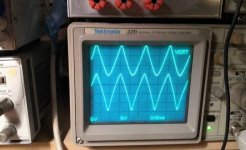
At the onset of clipping, bottom trace 50v/div, at cathode of top ECC88. It's anode is at 240v, cathode is 160v. Top trace speaker output 5v/ div.
I have just noticed I have two R9s in #8 circuit, I actually can't see whats infront of my nose sometimes, I think it may be some sort of dyslexic thing.
Attachments
Last edited:
The input and the output of the driver are in phase , so there is only negative feedback like you measured , no bootstrap in the grid of output tube ...
That trace on the scope should be a sine wave ? 😀 The signal in the anode of ECC83 looks the same ?
That trace on the scope should be a sine wave ? 😀 The signal in the anode of ECC83 looks the same ?
Initially I had a "pure" SRPP, without the 750k, the 270k and 1uF. This worked but I could not get enough voltage swing to drive the 6080, about >150v pk-pk. Adding the 750k, the 270k and 1uF, which does look a bit like the cascode's bias circuit pulls up the voltage at the cascode gives the required voltage swing. There could well be a more elegant way of achieving this, but it worked well enough so that is how it is now.
At the onset of clipping, bottom trace 50v/div, at cathode of top ECC88. It's anode is at 240v, cathode is 160v.
So, you have 80 VDC across V3 and hope to swing greater than 75 volts peak? And with the valve pulling grid current even at idle (also loading the bottom half valve)? That's just not going to go well.
YOS,
Chris
For SRPP the voltage between the tubes must be about half of the B+ , pretty obvious if you want maximum output swing .
Choke Coupled Driver?
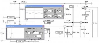
A choke has a great advantage, the energy stored in its field can take the output above the B+ line. It seemed this might be a better way to drive the 1/2 6080. But with NFB, there could be a problem with frequency response. Here is a solution that fixes part of the problems with this amp in its original form.
The first sim shows a 2 db rise with NFB at 17 Hz. The NFB is about 12 db. The Scope tells us the 6080 has 70V (50V/Div) bias, so 70 mA cathode current. I used two different models for the 6080 Based on different plate voltages, the results were about the same.
With NFB disconnected in the 2nd Sim the scope shews the driver is fully able to deliver full drive to the 6080.
The 3rd Sim shews distortion in the drive, a result of the NFB drive attempting to correct problems in the output stage.
It seems the output stage needs some work, the rest is AOK.🙂
Attachments

the 6336 being a low mu of 2 triode can not share the same rails as its driver tubes...the drive voltage swing to the 6336 grid is simply too high....imho....
the 6528 is a better tube to use if you want to use same rails....frank.pocnet.net/sheets/127/6/6528.pdf
the 6528 is a better tube to use if you want to use same rails....frank.pocnet.net/sheets/127/6/6528.pdf
The 5998 would be successful in this project. But it makes sense to continue on this one, I'll have a look at the 6080 in isolation later.🙂Does anyone care?🙄
Did anyone ever build this amp? I guess if they did it would 'sound OK'. Yuk, Yuk.
The original circuit was one of the first project / kits from the HiFi world magazine in the UK. They got Tim to design them a single ended triode amp, but Tim would have to come up with something "new". There seemed to be some kind of bust up between HiFi world and dP about this time. Hifi world acquired Andy Grove to design their projects, and this may have been a factor in dp offering the 859 in "kit" form through HIFi news.
I have heard one account from someone who heard the original, a they weren't overly impressed.
That trace on the scope should be a sine wave ? 😀
Not today, I like the triangle wave, I can see the nonlinearity more easily than a sine wave. In the previous picture the amp is clipping, so it looks a little worse.
So, you have 80 VDC across V3 and hope to swing greater than 75 volts peak? And with the valve pulling grid current even at idle (also loading the bottom half valve)? That's just not going to go well.
There is no grid current at idle, the cathode is 1.7 volts above the grid.
I agree that the drive circuit is "maxed out" but it can drive the output valve in to clipping, so that is good enough imo. And it actually sounds pretty good to me, and embodies dp hallmarks of dynamics and clarity, good solid bass and good timbral definition, revealing lesser recordings, but making good ones really good.
I have a few amps including ST70, Quad iis, ECL86 SE, UL84 UL SE connection and Schade feedback, 6V6 SE pentode of my own design, previous fave, very fast, but a little sugar coated, PP PCL86 cross between a Rogers and a red light district. Oh yes and a 2A3 Loftin White, which is nice but boring.
So the little 6080 holds its own easily in this company, and I wish I knew how it does it. It has a lot of capacitors in the signal path for example. I will work it out.
Last edited:
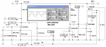
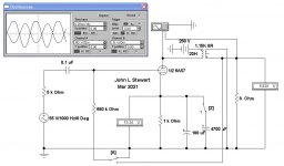
6080 SE Amp Output Stage in Isolation
Here it is driven by a 55V RMS signal thru a 5K source. Clipping has started. From previous experience I increased the cathode cap to 4700 microF, that helped. 100 microF in the original is not enough. Still only 4W, but about correct for the ~14W dissipation in Class A.
Switch 'A' allows a FB signal to be applied to the 6080 grid as in the original circuit, the effect is completely buried. We might expect that, the FB path is thru 680K to a 5K drive signal. It may have had some purpose with the 5 pF cap in the original. Would be dependent of the OPT characteristics, Anybody know what the original OPT was?
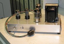
Would I build this? Probably not. But I did build a PP 6080 as a 'Proof of Concept' to illustrate boot strapping the driver stage to supply the very large drive voltage. Its a lab amp, I used a lab PS to power it, about 400V. The OPT is a Hammond. An easy 25W.🙂
Here it is driven by a 55V RMS signal thru a 5K source. Clipping has started. From previous experience I increased the cathode cap to 4700 microF, that helped. 100 microF in the original is not enough. Still only 4W, but about correct for the ~14W dissipation in Class A.
Switch 'A' allows a FB signal to be applied to the 6080 grid as in the original circuit, the effect is completely buried. We might expect that, the FB path is thru 680K to a 5K drive signal. It may have had some purpose with the 5 pF cap in the original. Would be dependent of the OPT characteristics, Anybody know what the original OPT was?
Would I build this? Probably not. But I did build a PP 6080 as a 'Proof of Concept' to illustrate boot strapping the driver stage to supply the very large drive voltage. Its a lab amp, I used a lab PS to power it, about 400V. The OPT is a Hammond. An easy 25W.🙂
Attachments
There is no grid current at idle, the cathode is 1.7 volts above the grid.
Your schematic in post #8 shows a voltage divider of about 3:1 between V3's anode and the bottom of its cathode resistor, feeding G1. That's a little more than +20 volts between G1 and the bottom of the cathode resistor. You can see how somebody on this thread would become worried that we're not seeing a true schematic. Now I'm expecting another surprise like triangle waves.
YOS,
Chris
- Home
- Amplifiers
- Tubes / Valves
- Tim De Paravicini's HiFi World 6080 amp modded by me.