Transistor 8 is connected with source and collector reversed. Schematic is correct, actual transistor connected wrong on pcb.
I will check it against the working channel.
Thanks
Tony
Transistor 8 is connected with source and collector reversed. Schematic is correct, actual transistor connected wrong on pcb.
I will check it against the working channel.
Thanks
Tony
It's the same way on the other channel.
Okay, I'll explain. The voltages you measured show 12 mA through xtr 8, but requiring a base current of 2 mA of xtr 8. This is typical of xtr operating in reverse mode. Xtr is not destroyed because xtr 4 limits C_E voltage of xtr 8 below E_B (E_C) reverse breakdown voltages.
Xtr 8 is not capable of pulling up voltage enough because reverse hfe is low.
Maybe other channel xtr 8 is just good enough to make it work. Maybe other channel xtr 8 is of different type.
Can you confirm that the actual transistor used for xtr 8 has C and E pinout matching that of pcb.
Xtr 8 is not capable of pulling up voltage enough because reverse hfe is low.
Maybe other channel xtr 8 is just good enough to make it work. Maybe other channel xtr 8 is of different type.
Can you confirm that the actual transistor used for xtr 8 has C and E pinout matching that of pcb.
Same transistor on the other board. Both look to be original and pin out to match the schematic. I will look for a sub and give it a try.
Xtr8 is passing 12.7mA. It is in saturation. Xtr3 is also passing the 12.7mA, but needing 12.9v from E to C because of limited base current or low hfe.
Xtr16 is sinking 14.0mA.
So where is the additional 1.3mA coming from?
Maybe disconnecting Xtr4, Xtr5, Xtr13 and Xtr14 will reveal if they are the source of the extra current.
An alternate thought - change the 470 ohm resistor attached to base of Xtr8 to 1K. Thus providing Xtr3 with additional base current.
Or increase supply voltage beyond 10 volts.
Last edited:
I will try these this weekend. I can go up to 30+/- volts on the bench. I have not had much luck in the search for a sub for the 2N4250a.
2N4250 Transistor | AlltronicsI have not had much luck in the search for a sub for the 2N4250a.
Alltronics appears to have a very few 2N4250 transistors left in stock.
A search seems to show that a 2N4248 is a substitute for the 2N4250 and that is more commonly available.
---Gary
My mistake. Xtr8 (2N4250?) is not defective or weak. In fact, it is operating in heavy saturation, where Ib is almost same current as Ic. No need to replace this device. It is doing what it is told.
The cascode device Xtr3 is the one I would question. But if there is an additional current sneaking into the path, then I would check Xtr4, Xtr5, Xtr13 and Xtr14.
Maybe measuring voltages of working channel will reveal where differences are at.
The cascode device Xtr3 is the one I would question. But if there is an additional current sneaking into the path, then I would check Xtr4, Xtr5, Xtr13 and Xtr14.
Maybe measuring voltages of working channel will reveal where differences are at.
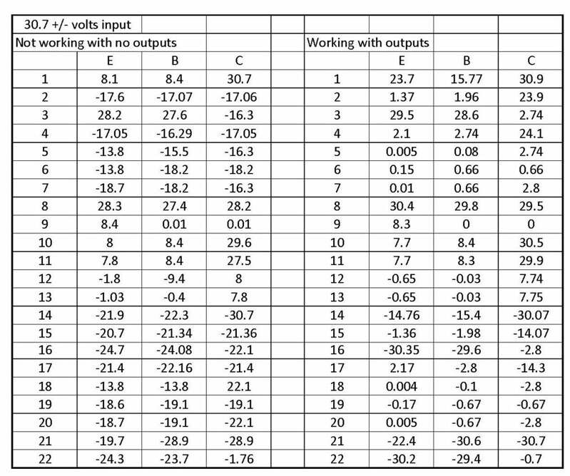
Here are readings at 30.7+/- volts. I think I may need to hook the outputs back up to the broken side before it is of real help.
 Volts30 with working
I put an updated copy of the voltage chart in post one.
http://www.diyaudio.com/forums/pass-labs/271817-threshold-4000-repair-need-some-help.html#post4267129
http://www.diyaudio.com/forums/pass-labs/271817-threshold-4000-repair-need-some-help.html#post4267129
Voltage on base of Q22 (and Q16) should be 2 diode drops higher than voltage at collector of Q21, i.e.
2 x 0.7v above -28.9v = -27.5v
Your measurements show -24.3 or 4.6v across the two diodes.
Conclusion: One (or both) of the two 1N914 diodes connected between base of Q22 and collector of Q21 is open.
Suppose to have ~2 ma thru Q22 and ~6 mA thru Q16. Measurements show ~15 mA thru Q22 and ~42 mA thru Q16.
I feel very unobservant. I checked these two diodes on the board when I had the resisters and transistors out for testing. Never noted one was backward. Voltages have changed for the better and draws less current. I think something is still amiss. See voltage chart at post one.
Last edited:
Voltage on base of Q22 (and Q16) should be 2 diode drops higher than voltage at collector of Q21, i.e.
2 x 0.7v above -28.9v = -27.5v
Your measurements show -24.3 or 4.6v across the two diodes.
Conclusion: One (or both) of the two 1N914 diodes connected between base of Q22 and collector of Q21 is open.
Suppose to have ~2 ma thru Q22 and ~6 mA thru Q16. Measurements show ~15 mA thru Q22 and ~42 mA thru Q16.
Good call by the way.
Thanks
Tony
Is it time to hookup outputs? I think once output is connected, feedback through 10K feedback resistor will force output to ~0 volts.
I see the four 1K series resistors not quite matched, allowing left output to be a few volts below 0v and right output to be a few volts above 0v.
I see the four 1K series resistors not quite matched, allowing left output to be a few volts below 0v and right output to be a few volts above 0v.
- Home
- Amplifiers
- Pass Labs
- Threshold 4000 repair. Need some help.