Looks like I have something going on in the negative side. #17 has -29.4 collector +3.76 emitter and +3.09 base. See if that helps.
Tony
Tony
Attachments
Last edited:

Hi, This is an old thread but looks like I'm in the same predicament as tonebells but looks like he did a substantial amount of work and provided a lot of good info. Did you ever get it working?
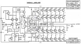
I have really been looking for a part list and schematic. I bought a 4000 that was not in working condition, someone before tried working on it and failed. It's now at my tech guy but is sitting on a shelf in parts for almost a year. He's stuck and needs a parts value list and a schematic. A lot of the values on the parts inside the amp have been removed and said he was working blind. I'll be going over to his shop later this week and take pics of the areas he's having trouble with.
Any help would be greatly appreciated. Would love to hear how this amp sounds when running well. Thanks
Those values in schematic in post 1 looks alright to me.
I repared two, one from -78 and one from -79. There was big difference between circuits, also soundwise.
Outputs have to be tested with low voltage and real current draw, not with DCA-75 or other whimpy tester. They often show that it works, but it fails with working current in circuit.
If I remember correct there was no exact bias instruction, "about 1 amp current draw from the wall, and about 50 degree C on heatsink"
Best regards
Figge

best to contact
Jon Soderberg
Vintage Amp Repair
ggle here for info or just ggle
he knows these amps
Jon Soderberg
Vintage Amp Repair
ggle here for info or just ggle
he knows these amps
Thanks Zen, I already know about Vintage Amp repair, the Soderbergs are awesome and they know their stuff but sadly this amp all packed up is about 100+ lbs (45kg) shipping there and back would be prohibitively too expensive; hence local service tech. plus I like the idea of supporting my local business's, we need to keep our local service tech guys going and any info we find and published here will be shareable for others in the future to repair their Threshold 4000 and enjoy
Thanks Trollet, I'll pass on the info when I see him and will let you know. CheersThose values in schematic in post 1 looks alright to me.
I repared two, one from -78 and one from -79. There was big difference between circuits, also soundwise.
Outputs have to be tested with low voltage and real current draw, not with DCA-75 or other whimpy tester. They often show that it works, but it fails with working current in circuit.
If I remember correct there was no exact bias instruction, "about 1 amp current draw from the wall, and about 50 degree C on heatsink"
Best regards
Figge
- Home
- Amplifiers
- Pass Labs
- Threshold 4000 repair. Need some help.