We plan on moving D9 on the Wolverine to the collector on the next pcb order. This was recently found.
Jeremy
Jeremy
"Does the diode position (emitter vs collector) mean a lot ?"
See post#2
https://www.diyaudio.com/community/...pensated-blameless-clone.397740/#post-7312926
See post#2
https://www.diyaudio.com/community/...pensated-blameless-clone.397740/#post-7312926
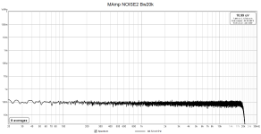

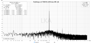
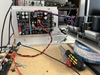
THD1k measurements.
The chain was : Viktor1k -> MAmp -> low impedance voltage divider -> passive notch filter -> post notch amp +40dB -> modded X-Fi USB HD
The chain was : Viktor1k -> MAmp -> low impedance voltage divider -> passive notch filter -> post notch amp +40dB -> modded X-Fi USB HD
Attachments
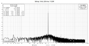


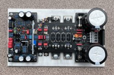
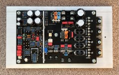
I'm still just at the beginning of tuning.
The first THD measurements give quite good numbers.
THD1k 10Vrms,20Vrms without load 0.00001%, into 4R 0.00006%
Three-pole compensation works, I tried TMC and TPC (jumper on pcb)
The first THD measurements give quite good numbers.
THD1k 10Vrms,20Vrms without load 0.00001%, into 4R 0.00006%
Three-pole compensation works, I tried TMC and TPC (jumper on pcb)
Attachments

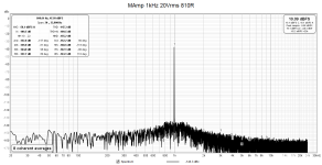
pcb v2 THD1k 20Vrms 8R (dBc, H1 is at 0dB, manual fundamental in rew)
Attachments
Last edited:
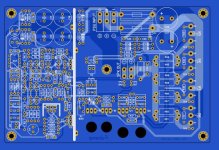
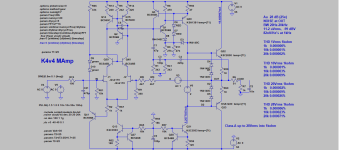
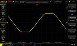
What is happening in the 40-50 MHz range in OL graph? Is that normal?I thought why not try the 3 pole compensated blameless amplifier clone. It worked out pretty well in simulation.
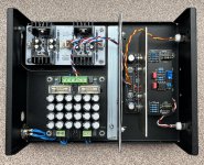
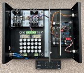
All important information is on the pictures.
Probably cancellation between the signal going through the compensation network and through the transistors.

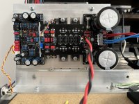
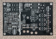
The fourth version of the PCB is ready. Version 4.1 is on the way (I've been waiting for customs clearance for 20 days now) and will be sold to local diyers.
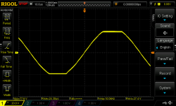
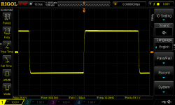
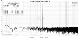
SSR3 is also part of the measurement - THD 1kHz 50W 4R . Classic output coil is not used, despite this, the amplifier is stable to capacitive load.
SSR3 is also part of the measurement - THD 1kHz 50W 4R . Classic output coil is not used, despite this, the amplifier is stable to capacitive load.
Attachments

- Home
- Amplifiers
- Solid State
- Three-pole compensated blameless clone