Can you elaborate? Is the design itself accounting for this view or do you find that output coils are generally unnecessary?
An output coil is required. I just changed the design. Instead of the classic air coil, I started using the inductance of the wire that connects the amplifier board and the output terminal of the chassis. The amplifier is also designed so that 0.1uH inductance is sufficient for stability. ( PM > 60 deg, GM > 15dB, stable into 15nF II 4R load without coil).
IMHO, If you are aiming for the -120dB thd level, it is better to have the coil outside the amp pcb.
IMHO, If you are aiming for the -120dB thd level, it is better to have the coil outside the amp pcb.

Is this a triple output? What is the function of Q1/Q4 ?
yes, triple. Q1,Q4 are error correction transistors [not my invention 😢]
Last edited:
LKA, if I want to add one more pair of output devices, do I need to increase drivers/predrivers current?
25mA seems like enough for 3 pairs or even 4?
Are you sure 2 pairs will handle 200W at 4 Ohms?
25mA seems like enough for 3 pairs or even 4?
Are you sure 2 pairs will handle 200W at 4 Ohms?
yes, you can add one more pair.
sure, two pairs of IRFP240/9240 can handle 200W/4R (no secondary breakdown, DC SOA 100V 1,5A )
sure, two pairs of IRFP240/9240 can handle 200W/4R (no secondary breakdown, DC SOA 100V 1,5A )
Last edited:
I am curious about this statement, do you think the relatively poorer performance at 10k is specifically related to Cosmos ADC than what is generally observed with other ADC's, do you have any idea what may be the reason?Cosmos ADC is optimized for 1kHz, at 10k(20k) it has "weak" performance.
I don't know if this is relevant, but sigma-delta audio ADCs often have the noise increase quickly above 20 kHz.
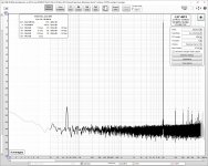
The ES9822PRO uses ESS techs distortion minimising software within the DSP signal processing of the ADC.I am curious about this statement, do you think the relatively poorer performance at 10k is specifically related to Cosmos ADC than what is generally observed with other ADC's, do you have any idea what may be the reason?
ESS comment that this can be used to tune out distortion caused by the input stage of the ADC but in reality it reduces the self distortion of the ADC itself.
To do this properly you need a very low distortion signal source but for the best results you have to manually set a couple of coefficients within the software for the lowest HD2 and HD3. You could tune this for the best performance at any frequency of interest but 1k is typically chosen.
If 1k is used then the performance usually remains constant from 20Hz up to some point (say 5k) but then loses efficacy. You could tune for lowest distortion at 10k but then it would measure higher below.
Generally speaking I get the feeling DAC & ADC IC manufacturers business reaching lowest possible marketing distortion figures is by baking in some kind of secret sauce microcode into their chips a la VW diesel gate XD ie. the chip would go into a special feature mode when it sense a stable 1 kHz tone for instance. Well, I can't tell for sure so it's only wild speculations, but who could if it's some perhaps plausible microcode maybe/only reachable by some secret instructions not publicly given?
Interesting speculation, but if you understood the architecture of modern pipelined sigma-delta converters you'd realize that's much harder than just being a good performer in the first place. Sigma-delta is inherently very linear because it counts charge packets (put very basically) then decimates and filters. Where in that process could you recognise a "stable 1 kHz tone" other than at the end using an FFT, by which time you add lots of extra delay for the FFT processing on top of the sigma-delta pipeline and digital filter delays. It would be a bit like adding an mp3-encoder-decoder pair on the output since it would be like perceptual masking - and that can only work in an ADC, a DAC's performance cannot be faked!
The magic is in the front end analog and sigma-delta modulator for an ADC and output modulator on a DAC
The magic is in the front end analog and sigma-delta modulator for an ADC and output modulator on a DAC
The BAT54 diode has a maximum reverse voltage rating of 30V. Maybe you need to select a different diode for this location?MOSFET updated schematic
- Home
- Amplifiers
- Solid State
- Three-pole compensated blameless clone