Power surprise!!
I just compared my little lm1875's against lm3886 in a head to head shootout. Guess what? With a bit of voltage and a huge heatsink, the lm1875's outperformed the lm3886, on sheer power, and by twice. Yes, drove both to clipping and then rolled back until the point where a tad of dynamics appeared. . . 35 clean watts from LM1875, and not quite 20 for LM3886.
Of the two, LM1875 was cleaner.
Are these results unusual?
Given that the LM1875 is rated at 20W RMS yes I would say that is very unusual! What rails were you using?
my system
This is interesting reading. I have read several places that using small capacitors will improve sound quality. Even though I haven’t experimented with this, it doesn’t seem to be a reality in my ears. F.x. les capacities gives les stabile power supply and the PSRR on any on these chips isn’t that god.
I have also read several places that the 1875 sounds better than the 3886. This on the other hand gives god meaning. The 1875 chip has smaller silicon area, because it’s not made to deliver as many amps (I think its 4A and 11A?) as the 3886. Therefore it is a bit faster.
My own system is two 2½ way active loudspeakers. My filter is based on AD810 in input, AD8620 in the bas and mid/base section and an AD8065 on the high. This way the music is feed to 3886’ers from a low impendence output and they seem to like that. The fact that there is nothing between my bass and the 3886’es gives a very firm and potent bass. I couldn’t believe it the first and my smile was so big 😀
My power supply for those 3 amp’s are a trafo on 225VA 2*18V out and a total of 60.000 uF. Right on the 3886’s I have placed two 470uF ultra low ESR High Current capacitors. I’m using a gain of -12 on the 3886’s. To protect my tweeter from DC, I have placed a 15 uF polyprop in series.
I’m very happy with the result. No way ill ever go’ back to ordinary passive filter ever again.


Description and pictures in Danish on http://www.hifi4all.dk/forum/forum_posts.asp?TID=44900&KW=bdef&PN=0&TPN=1
This is interesting reading. I have read several places that using small capacitors will improve sound quality. Even though I haven’t experimented with this, it doesn’t seem to be a reality in my ears. F.x. les capacities gives les stabile power supply and the PSRR on any on these chips isn’t that god.
I have also read several places that the 1875 sounds better than the 3886. This on the other hand gives god meaning. The 1875 chip has smaller silicon area, because it’s not made to deliver as many amps (I think its 4A and 11A?) as the 3886. Therefore it is a bit faster.
My own system is two 2½ way active loudspeakers. My filter is based on AD810 in input, AD8620 in the bas and mid/base section and an AD8065 on the high. This way the music is feed to 3886’ers from a low impendence output and they seem to like that. The fact that there is nothing between my bass and the 3886’es gives a very firm and potent bass. I couldn’t believe it the first and my smile was so big 😀
My power supply for those 3 amp’s are a trafo on 225VA 2*18V out and a total of 60.000 uF. Right on the 3886’s I have placed two 470uF ultra low ESR High Current capacitors. I’m using a gain of -12 on the 3886’s. To protect my tweeter from DC, I have placed a 15 uF polyprop in series.
I’m very happy with the result. No way ill ever go’ back to ordinary passive filter ever again.
Description and pictures in Danish on http://www.hifi4all.dk/forum/forum_posts.asp?TID=44900&KW=bdef&PN=0&TPN=1
I am curious as well...richie00boy said:Given that the LM1875 is rated at 20W RMS yes I would say that is very unusual! What rails were you using?
Fixed that shouting BStRD!!! LM3886 is inferior.
30+30DC with:
Artic Ceramique for heatsink compound (heatsink hot, chip is cool).
That power is happening with 1uf decoupling (input filter) cap. Although I do prefer the bigger presentation from a larger value like 2.5uf to 3.3uf decoupling cap, which is less power but more dynamics and bandwidth.
At least LM1875 has this option that's so easy to exploit.
I didn't realize that this common feature was a luxury until I purchased a LM3886 (hideous in comparison to its little sister).
As it turns out there's no human-noticable difference in output power between LM1875 and LM3886 IF given the same voltage.
Of course there's a big difference in thermal management.
I do have both amps.
One of them sounds nice.
That's LM1875 (sounds nice).
So, if you've got 33+33 DC or Less then you could make an upgrade by throwing out the LM3886 and putting in a better-sounding LM1875. 😉
richie00boy said:Given that the LM1875 is rated at 20W RMS yes I would say that is very unusual! What rails were you using?
30+30DC with:
Artic Ceramique for heatsink compound (heatsink hot, chip is cool).
That power is happening with 1uf decoupling (input filter) cap. Although I do prefer the bigger presentation from a larger value like 2.5uf to 3.3uf decoupling cap, which is less power but more dynamics and bandwidth.
At least LM1875 has this option that's so easy to exploit.
I didn't realize that this common feature was a luxury until I purchased a LM3886 (hideous in comparison to its little sister).
As it turns out there's no human-noticable difference in output power between LM1875 and LM3886 IF given the same voltage.
Of course there's a big difference in thermal management.
I do have both amps.
One of them sounds nice.
That's LM1875 (sounds nice).
So, if you've got 33+33 DC or Less then you could make an upgrade by throwing out the LM3886 and putting in a better-sounding LM1875. 😉
Re: Fixed that shouting BStRD!!! LM3886 is inferior.
p.s. I always liked the LM1875 too.
That defies the laws of physics! Great compound you have there!danielwritesbac said:
(heatsink hot, chip is cool).
p.s. I always liked the LM1875 too.
Played around and got more power than LM3886.
Yes it is. From the age of the original Athlon computer processor, the Palimino, the roasting hot Barton, and the Pentium 4 that would slow down if it got hot---comes Artic Ceramique.
It had to be great or it wouldn't work.
And with a 44vct transformer, the soundfield (per each channel) is audiophile size. Finally.
Some of that whopping power boost can be spent away for larger size input filter cap, and there's audiophile grade caps available to tailor the tone of the amp. The caps graded "warmer" are very, very pleasant with the gainclones.
That can take the LM3886 up to useful status, or take the LM1875 to high-fidelity nirvana land. 😉
paulb said:
That defies the laws of physics! Great compound you have there!
p.s. I always liked the LM1875 too.
Yes it is. From the age of the original Athlon computer processor, the Palimino, the roasting hot Barton, and the Pentium 4 that would slow down if it got hot---comes Artic Ceramique.
It had to be great or it wouldn't work.
And with a 44vct transformer, the soundfield (per each channel) is audiophile size. Finally.
Some of that whopping power boost can be spent away for larger size input filter cap, and there's audiophile grade caps available to tailor the tone of the amp. The caps graded "warmer" are very, very pleasant with the gainclones.
That can take the LM3886 up to useful status, or take the LM1875 to high-fidelity nirvana land. 😉
Calculator on the blink.
My calculator was off. My fault. I had used "N" diode.
I meant to say 34+34 volts DC and more is doable (just watch the thermals), and then the luxuriously wide presentation appears (as if you had used a preamp).
The 30+30 is almost enough.
Down at 20+20 DC, the LM1875 can be a bit masked for my tastes.
So, there's my thoughts on the voltages.
I think I'll have some fun and try to "fool" the limiter--change 100k to 120k or 150k (or more), change 22k to 56k, change 1k to 2.2k or more, (all carbon 1/2 watt, tube-ish sound) change input filter cap to 3.3uf or higher nice warm BlackGate. Most LM, higher speed raises the limit. Break sheetrock. 😉
Re: Fixed that shouting BStRD!!! LM3886 is inferior.
That's only true as long as the chip can handle the current drawn by the load. The 3886 is capable of sourcing/sinking more current than the 1875, meaning it can supply more output power into lower impedance loads.
danielwritesbac said:As it turns out there's no human-noticable difference in output power between LM1875 and LM3886 IF given the same voltage.
That's only true as long as the chip can handle the current drawn by the load. The 3886 is capable of sourcing/sinking more current than the 1875, meaning it can supply more output power into lower impedance loads.
LM1875 doesn't have the SPiKE circuitry implemented, maybe that's the reason why it can sound better than LM3886?
Beside that I also prefer LM1875 because of it's simplicity.
I use them in a balanced/differential topology.
Beside that I also prefer LM1875 because of it's simplicity.
I use them in a balanced/differential topology.
That's odd!! The manual says that the chip contains a similar protection. I thought it was Spike.
Maybe the 100k/10k NFB partially lobotomizes the protection schemes?
This was evident in using 56k/1k/47uf NFB in LM3886 because the Spike protection was then half as likely to engage in purposeful clipping.
There is reference in the LM3886 manual of testing power output without spike engaged, which is the only condition for it to actually achieve its powerful claims without spike-inspired noise. ???????????
There's no obvious switch, so I looked for examples that don't behave as poorly as LM3886. An example was on my desk. LM1875.
In addition, doubling the LM1875's input circuit layout and "pasting" it onto LM3886 also further reduced the malice from setting off the Spike--and it further leveled the frequency response.
I also changed to carbon resistors because they work so very well in my LM1875's.
The end result was restricing the LM3886 to the audio bandwidth, at a level frequency response and double the power because audio-only is less work.
So, my idea of copying the support circuits of LM1875 onto LM3886. . . was an accident. WOW!!
No wonder that everyone thought I had lost my mind and/or whoever actually did the mod was so confused on why it works.
I don't know either.
But I'm grateful that I didn't have to dispose of the LM3886 and substitute TDA7294's just to get rid of the Spike noises.
None of these things have serious power. However!! There's a reference to using LM1875 as the drive for power transistors. I'm SO very interested in understanding how to do it.
danielwritesbac said:Maybe the 100k/10k NFB partially lobotomizes the protection schemes?
This was evident in using 56k/1k/47uf NFB in LM3886 because the Spike protection was then half as likely to engage in purposeful clipping.
Daniel, the external gain setting resistors should have very minimal, if any, effect on the protection circuitry.
How did you know the Spike protection was half as likely to be engaged? Did you verify this with a scope or are you just assuming?
danielwritesbac said:There is reference in the LM3886 manual of testing power output without spike engaged, which is the only condition for it to actually achieve its powerful claims without spike-inspired noise. ???????????
Of course its power output claims are without the protection circuit activated. Almost all manufacturers do that.
With lack of documentation, this repair was functional science used to determine a baseline. Thus "working hypothesis" is the term.
That means it does work.
The reason is unknown (its undocumented).
It wasn't measured before and after. My apologies! I was so happy when it finally worked that I put it immediately into service.
This is the difference between obvious clipping at 20 watts. . . or, after mod, pinning down power meter like a champion wrestler, holding it pegged as if KO'd and and not clipping one bit.
Let up on the force a bit, and a power meter indicates that dynamics are satisfactory because they are beyond its measure.
There is breif mention in some of National's documents of testing maximum output and maximum fidelity achieved simultaneously with Spike specifically shut off or hindered.
There is NO switch.
There IS a way.
It is without a switch.
The difference may not have been to the exact percentage of 200%, although it was a very beneficial difference and the resistor values that caused the benefit were at 200% of the original, within an otherwise matching proportion.
There is an equal chance that either this is the undocumented Spike behavior switch or the switch is worked by freezing the chip. After an earlier experience, I didn't want tank caps in the freezer with my ice cubes again, so the second possibility remains untested.
Ah, not a scope, but do have a 330 ohm resistor and a 1/8" cable to pipe a signal into the computer where I can record. . . and then look at the waveform.
The LM1875 is (was) remarkably different.
After getting rid of the excruciating metal resistors, the frequency response had flattened out.
The two performed similarly (at low volumes), but the LM3886's still came up short, quite easily outdone for fidelity and force by LM1875's. Curious!!!
Assuming that the previous resistors had caused trouble with LM3886, I decided to try a value that is both within specs for LM1875 and LM3886--and still using carbon* like the LM1875 I had measured.
*Carbon resistors had helped in the task of restricting the audio amplifier to the audio bandwidth because carbon is less likely to carry ultrasonics. Amplifying only audio makes a stronger amplifier.
There was some experimentation and workarounds before this was brought into balance. Since the kits I had received were unable to perform their advertised duties, I was shopping Thompson TDA7294, but in its documentation was a nice surprise--match the layout to increase the bandwidth and then confine it to the audio spectrum to increase the power.
Okay!!
Great luck!!! Its layout matched up with LM3886, and right there was the clues on how to turn it up a notch--without clipping.
Using only approximate averages, the proportions from LM3886, the idea of LM1875 and the documents from seven different amplifiers, especially the matching idea from Thompson, the results are. . .
LM3886TF:
56k, 1k NFB, with the 47uf cap in place.
56k, 4.7uf-2.2k-A50K* Input
*A20k pot was too much load for headphone level devices like television and battery power Ipods that run their batteries out if used on max--application specific.
This does not require a preamp or cause want for a preamp.
It was tested with 40+40 volts DC.
Previous (in provided condition), audible clipping would occur before 20 watts steady power. However. . .
Post (after mod), the power was satisfying with no clipping in the treble, yet some light clipping in the bass. . . just like a Thompson chip would do--just like a Spike system wouldn't do.
Unfortunately, I was so glad that the fight was over, I just put the finished power amp stages into the amplifier chassis, and immediately into service (that is of great benefit).
It was cause for dancing, and not just me! 😉
Hi Daniel.
Your terminology is confusing me a bit, so would it be possible for you to clarify the exact configuration of your amps? It would be best to use the reference designators used on the typical application schematic shown in the datasheet for each chip. For example, look at page 1 of the LM3886 datasheet and tell us what you're using for Rin, Rb, Ri, Ci, and Rf.
From your last post it sounds like you're now using Rin=20k, Rb=?, Ri=1k, Ci=47uF, Rf=56k.
As far as testing max power output without the Spike protection activating, you simply test the chip's output up to clipping with an adequate heat sink... There's really not much more to it. The protection will kick in ONLY if you push the chip too far for too long. Changing the gain of your amp should not have any effect on the Spike protection. Perhaps your amp is oscillating and that is what is causing the protection to kick in and degrading the sonics. Hard to say without seeing a detailed picture of your amp.
The feedback network and the values of the parts used in it set the bandwidth of the amplifier (as well as any components used for input filtering) NOT the type of resistor used (unless it's really crappy). Feel free to say that carbon composition resistors sound different than metal films but don't spread that BS.
Your terminology is confusing me a bit, so would it be possible for you to clarify the exact configuration of your amps? It would be best to use the reference designators used on the typical application schematic shown in the datasheet for each chip. For example, look at page 1 of the LM3886 datasheet and tell us what you're using for Rin, Rb, Ri, Ci, and Rf.
From your last post it sounds like you're now using Rin=20k, Rb=?, Ri=1k, Ci=47uF, Rf=56k.
As far as testing max power output without the Spike protection activating, you simply test the chip's output up to clipping with an adequate heat sink... There's really not much more to it. The protection will kick in ONLY if you push the chip too far for too long. Changing the gain of your amp should not have any effect on the Spike protection. Perhaps your amp is oscillating and that is what is causing the protection to kick in and degrading the sonics. Hard to say without seeing a detailed picture of your amp.
*Carbon resistors had helped in the task of restricting the audio amplifier to the audio bandwidth because carbon is less likely to carry ultrasonics.
The feedback network and the values of the parts used in it set the bandwidth of the amplifier (as well as any components used for input filtering) NOT the type of resistor used (unless it's really crappy). Feel free to say that carbon composition resistors sound different than metal films but don't spread that BS.
I'm off to exploit some LM1875's now. 😉
Rear channel amps!!
How do you make a delay circuit or reverb?
How do you make a differences input slightly favor the left and another that slightly favors the right?
I'm looking for nothing but LM1875's, diodes, caps, resistors and one transformer. The project is to decode stereo rear surround sound from an analogue line.
I'd like this rear channel partner to be inexpensive, and be quite simple enough for anyone to assemble it.
I'm just having a bit of trouble with a Stereo differences input and whatever sort of delay or reverb for rear channels.
BWRX said:Hi Daniel.
From your last post it sounds like you're now using Rin=20k, Rb=?, Ri=1k, Ci=47uF, Rf=56k.
If carbon sounds different, it is a filter. A filter is capable of altering bandwidth from interreaction via decreasing the amplifier's workload, isn't it? Help? 😉
Terminology?
You're referring to page 8 of lm3886.pdf? Can't.
There's no photograph of a fully functional "full draft" input circuit in that document.
Let's refer to
http://www.electronics123.net/amazon/datasheet/k50.pdf
The common LM1875 kit, K50.
See the bottom of Page 2 of K50.PDF
Now we can both reference all of the parts.
For an LM1875 design ported over to LM3886:
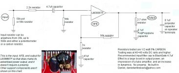
INPUT:
K50.pdf
X1 to X2, a 50k pot or 56k resistor. (Rin)
R1 2.2k, the in-series resistor (Rb)
R2, omit
R3, 56k, the input load
C1, 4.7uf the input filter cap (C) (specifically that blackgate that everyone was pasting onto Sonic's T-amp here at diyaudio.com)
NFB:
K50.pdf
R4, 1k (Ri)
C3, 47uf (elegant cap in Brian's kit) (Ci)
R5, 56k (Rf)
Example.
INPUT:
Brian's kit at chipamp.com:
An A50k potentiometer. (Rin)
2.2k added onto the signal input terminal. (Rb)
22k, changed to 56k*
*Input loader is necessary when you use (C)
1k changed to 4.7uf. (C)
NFB
Brian's kit at chipamp.com
22k changed to 56k. (Rf)
680 ohms* changed to 1k* (Ri)
don't use the middle hole, reach to the next and engage the. . .
47uf (Ci)
Input loader, as seen in R3 in the K50 document for LM1875--its necessary to load both sides of an input filter cap for optimal performance.
Input loader, as seen in some thompson documents--its necessary to match with Rf (both are 56k in my example) if one wishes optimal power output.
I sincerely hope that I didn't make an error. Please report if so. 😉
Hi Daniel,
the last post shows your schematic.
The output has half of the Thiele Network.
By omitting the series inductor, the output cap is straight across the chipamp output and reduces the phase margin. This can lead to instability and ringing or even oscillation. The inherent inductance of the wire connection from output pin to speaker terminal will help a little but I suspect that wire inductance is just too low to prevent the stability margins being compromised.
I wonder if some of the weird results you have found are due to oscillating chipamps!!!!!
I would not take much convincing to believe that Spike could easily be triggered prematurely by reactive loading and oscillation.
Secondly,
the high pass filter on the input passes more low frequency than the NFB can handle. The voltage across the 47uF will be significant and lead to some odd sounding results.
The input filters (both HF and LF) should define the bandwidth of the amplifier. The NFB should be set up at a slightly lower frequency.
I suggest you alter the 4.7uF + 56k =263mS to around 80 to 90mS and increase the NFB from 47mS (47uF + 1k) to around 130 to 150mS.
However the 4.7uF is not in isolation. The DC blocking capacitor in the source equipment is also in series with the power amplifier DC blocking cap. If both the source and the receiver have caps fitted then your time constant must take account of this topology.
Finally,
fit an RF (low pass) filter to the power amplifier input.
AndrewT Thanks for the calculations. . .
Please include the average ESR of the little polyester bubble cap on the speaker terminals. The average for that cap at that size is 10 ohms ESR, as in 5 ohms to *cap* to 5 ohms. The chart specifically states polyester. 😉 This is an ac signal with this cap as a load upon it, so . . .
Please recalculate including ESR?
- Home
- Amplifiers
- Chip Amps
- Thoughts On LM1875 Gainclones