...and finally the fialment examination in superposition
Well, this is more "tense". One slight error and one needs to remake all measurements 😡 (occurs several times)
And is necessary to make one, play with it and repeat to precise one-time adjustment or becomes a big mess
Thanks smoking-amp by suggesting this, so I insisted in subject and obtain a more clean graph
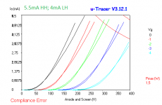
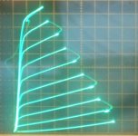
In section one (the high-µ), is impossible to match. With low heater, the curves become more J-shaped. With high heater, the curve become more /-shaped. I bet some HD (distorition) change, maybe even dramatically, but I prefer to play with a preamp and my FFT first...
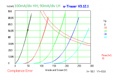
In output section, the change is small, but the J-/ behaviour is the same. is easy to see when the tracer are making the curves.
Interesting...
Remark: the tube tested here is a 6EM7 GE coin base NIB NOS (is a other sample, not same from previous 6EM7 graphs)
Well, this is more "tense". One slight error and one needs to remake all measurements 😡 (occurs several times)
And is necessary to make one, play with it and repeat to precise one-time adjustment or becomes a big mess
Thanks smoking-amp by suggesting this, so I insisted in subject and obtain a more clean graph
In section one (the high-µ), is impossible to match. With low heater, the curves become more J-shaped. With high heater, the curve become more /-shaped. I bet some HD (distorition) change, maybe even dramatically, but I prefer to play with a preamp and my FFT first...
In output section, the change is small, but the J-/ behaviour is the same. is easy to see when the tracer are making the curves.
Interesting...
Remark: the tube tested here is a 6EM7 GE coin base NIB NOS (is a other sample, not same from previous 6EM7 graphs)
Attachments
Last edited:
A set of MC275 transformers came up on the Bay...2x 42kn6 for the outputs and 2x 6LU8's to handle the front end. OPTs are trifilar so the tertiary winding runs the kn6 SG's. My guess is that the power on each channel will be well north of 100 watts...
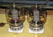
I was wondering how the 4-250's would go as zero bias triodes; got plenty of them & 4-125's.
Phil
Phil
hey smoking-amp, i got a pair of 4-250's, what do you say about using a crazy drive on those on push pull circuit? crazy eh? 😀
subscribd
Looking at the Eimac datasheet for the 4-250A in class AB1, you will need 0 to 600V at 23 mA to drive the g2.
Got another transmitting tube for the driver tube? And then a driver for that one too.
https://frank.pocnet.net/sheets/140/4/4-250A.pdf
Got another transmitting tube for the driver tube? And then a driver for that one too.
https://frank.pocnet.net/sheets/140/4/4-250A.pdf
Looking at the Eimac datasheet for the 4-250A in class AB1, you will need 0 to 600V at 23 mA to drive the g2.
Got another transmitting tube for the driver tube? And then a driver for that one too.
https://frank.pocnet.net/sheets/140/4/4-250A.pdf
yes, crazy drive is toio crazy after all...😀
That earlier 4D32 design didn't look too likely for Crazy drive either at 300 Volts spec'd for g2. But I guess they only wanted 6 Watts from the 50 Watt tube.
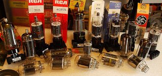
The TV Sweep tubes work like wonders though, using Crazy drive. All those cheap $1 TV tubes I got way back are looking WAY better. 🙂 🙂 🙂
The TV Sweep tubes work like wonders though, using Crazy drive. All those cheap $1 TV tubes I got way back are looking WAY better. 🙂 🙂 🙂
Attachments
Last edited:
Crazy-Drive just may give me a mad plan.
At work, Ive got hold of a 200W 7-channel Carlsbro PA/Stage-amp. Fairly good condition but the Mains trans has an O/C secondary. This has a stacked supply, one of 400V and another (The dead supply) of 320v sitting on top supplying the 4 KT88 plates that Should be in it.
The KT's have been subbed at some time in the past with a mix of very tired EL34 and not quite so tired looking KT77...
I doubt its worth trying to buy a correct Mains Transformer and also a new set of KT88 for this thing, be more than its worth I'm guessing....
I have a big ole Gresham Oil-Filled Mains Trans of 500V 500mA secondaries and some high current 6.3V and 5V windings--I guess at a push I can squeeze in the case in place of the O/C Mains Trans. in there.....
The oil-filled doesn't have any bias windings or much of anything except the C.T 500V and heaters.
Ive also got numerous PL519, some nos, some very well used and some just 'run-in'
Thinking I may bung four PL519's in place of the KT88 and drive 'em crazy, my only concern is with the new trans, after rectification and smoothing, Ive got 700V (Same more or less as original scheme) that the PL519 may find stressful, even though the data sheet indicates 7000V Va-max, this is for pulse non conducting state. Normal Va is a lot lower I would assume.
I would also need to add an additional heater trans for the PL519 heaters and derive a 400V supply for the pre-amp/driver stages but that's not hard to do.
--What do you reckon....?
Last edited:
PL519 lists 700V as max cold B+, so should just work. C input B+ usually drops 10% with loading. George (Tubelab) has run Sweep tubes at 600V+ routinely.
Seeing as the B+ was similar before, the OT primary Z is probably suited to that B+. The PL519 datasheet gives graphs on grid2 resistance to protect the grid, so I would put some current limiting in the grid2 drive. Looking at Mickeystan's Crazy drive design using a Mosfet follower:
http://www.diyaudio.com/forums/tube...nificent-television-tubes-67.html#post4675483
Just add a resistor in series with the Mosfet follower drain circuit to limit grid2 current to maybe 50 mA. (can customize later, once the operational levels are known) For INITIAL testing, one might put a HV SS diode in series with the grid2 to prevent any electron emission from a hot grid2. This shouldn't be a problem once the design is stabilized (would likely distort some with the diode left in there). Crazy drive should require less grid 2 drive swing than just g2 drive alone. May only need 100V of grid2 drive swing with the lower plate current using 650 V B+ (and the approx. 25% supplemental drive from the resistively driven grid 1 in Crazy drive mode).
Looking at the 26LX6 Crazy drive info, around 2.7K from g2 to g1 and around 1K from g1 to cathode worked. (Rg2g1 usually in the 4K to 2K range, and Rg1k usually in the 2K to 500 Ohm range) Probably a good ballpark resistor set to start with for the PL519 in Crazy drive. Be careful not to overdrive grid 1 in the now positive territory. Some current measurements of grid1 with a DVM can indicate average current and voltage (+ with respect to the cathode). Doesn't take much resistive grid 1 drive to linearize the tubes, no need to get grid 1 hot at all.
You will need some N Fdbk somewhere to lower the output Z of the amplifier, Crazy drive looks like a pentode output in it's native mode. A simple local resistive Schade Fdbk network to a pentode driver plate could help, but the g2 drive or Crazy drive approaches have 1/Mu reduced loop gain (around the output tube only) versus normal grid 1 drive. So a local loop may require N Fdbk to the driver cathode(s) to pick up enough gain. Of course global N Fdbk alone could work too, or could supplement simple Schade Fdbk.
Last edited:
Ah--Thats good news!
Thanks for thinking of this for me--Ive dabbled with straight Screen-drive before, but not any other Crazy ideas...
As an initial op-point, I was thinking of say 40mA per tube in PPP and at 700, would give 28W P-Diss per tube idling.
The original scheme used the KT88 in native Pentode arrangement and uses a 2200/8 ohm O/P trans.
There is global F/B and as this is a Stage amp, I guess it doesnt need to have perfect distortion figures, but will play around--see what will happen...
The existing driver is direct from the LTP phase-splitter, and F/B is applied to the g1 of the second half...
I think just 2 PL519s will give at least 150 Watts output (using maybe a 3.3K or 2.5K Zprimary) from what George has said before. Using 4 of them will double both grid gm's, so even less driver voltage swing would be needed. I would guess that just 2 PL519 could drive the 2200 Ohm P to P OT. (one PL519: 500 mA max DC current, 1500 mA peak DC current using +185 Vg2) Of course, lower current per tube will last longer. Seeing as Crazy drive gives near perfect output tube linearity, you may want to listen to the amp for a while longer. 🙂
On the op-point:
g2 drive amps usually operate closer to class B with high efficiency. So I would guess Crazy drive can do similar. This all depends on how the P-P tube characteristics overlap around crossover. Some testing needs to be done with Crazy Drive to see how well crossover is handled, and so how low the idle current can be. But I expect some idle power economization will be possible over usual class AB setups.
Last edited:
Looking at typical Crazy drive plate curves, they give near constant effective gm over the full current range (except at very low currents). So setting the idle current too high in P-P could produce gm doubling in the overlap range. So the optimum P-P conduction overlap range is going to be smaller than for typical class AB. Hence, lower idle current expected for best results. Some tweaking of the Rg2g1 and Rg1k resistors may optimize the overlap region too. On the other hand, a little selected gm doubling could overcome the low permeability of typical OT steel cores near crossover. FFT analysis called for.
Attachments


Last edited:
Wow--Thanks for the extra info. I'll look for crossover and trim the bias to minimise, then maybe trim the Crazy R-pair
What effect does the Cathode-resistor have in this scheme? I notice its a 1 ohm in most schemes Ive seen, Can this be trimmed to affect a little degenerative neg FB.....
It seems then, there is nothing but good relating to this scheme. I keep thinking--there must be a downside somewhere....
The chassis has four sockets for the original tubes so I might as well just replace all 4 for the magnoval 9-pin and use PPP, possibly I may not need to gain more voltage P-P drive than the 80 odd V I Think Ive available at the moment--We'll see on that one...
I'm no musician, but have a friend or two who are, When this thing is built and tested as far as I can go with my limited equipment (Scope and sig-gen etc) I'll pass it over--let 'em run it to the max, see what they think!
My experience with the PL519 is that the datasheet is -just like for all TV sweeps- very conservative. The plate can handle at least 1/3 more heat than the 45W abs max. No glow at 60W.
700V shouldn't be any problem either. Even the EL34 is rated for 800V like the KT88.The limit is the socket: the TT21 is the same as the KT88, but is rated for much higher voltages due to the plate coming out on the top instead of the socket.
I got way more than 100W out of a pair of PL509 in classic pentode, running at less than 500V into 2k. I'd have to look up the exact numbers.
I've got some experiments planned for higher voltages 600ish) when I got some OPTs that can handle that kind of power.
I have no doubt that George (Tubelab) can get 200 Watts out of a pair of PL519. Just a question of how conservative one wants to be for tube longevity. I know the 6KG6s have gotten fairly expensive lately. 6HJ5 and 21LG6 are still around $4. 6CB5 and 26DQ5 are cheap. And 21HB5A and 12GE5 were $1 recently, got a big box of all of them. All the parts are piled up here to build a Crazy Drive amp, including some Edcor OTs, just have to get some spare time. Other priorities keep interfering rudely.
"I keep thinking--there must be a downside somewhere...."
Well, g2 drive historically is susceptible to g2 overheating, meltdown, and emitting electrons to the plate catastrophically. Especially if over-driven. Fortunately, Crazy drive reduces the g2 voltage and Wattage requirements, and with it comes tube linearization effects that are beyond any reasonable expectation. I still don't get how it straightens out the plate curves and sharpens the knees (this all beyond the gm linearization, ie equal spaced curves). If this had been recognized in the 1950s, I think every tube audio amp ever made would have used it. Of course, a HV Mosfet follower for the grid2 is what really makes it practical now.
The 1 Ohm resistor in the cathode is probably for idle current setting, and likely is a fusible metal film R for OT protection. Current limiting the g2 drive(s) should be a big protection against Bass Guitar players trying desperately to get distortion out of a truly linear amp.
-
Last edited:
The PL519 is prob overkill then for PPP in this amp....
Only Other tube I have is the 6HJ5, Ive 10 NOS of these. Maybe four of those would be better, save me messing with additional heater supplies and somewhat safer--No top-caps, Pretty sure Ive got the ceramic Duodecar sockets somewhere too.
The thought of someone pulling the back off the amp even with insulated caps and bunging a hand in there, doesn't bear thinking of with 700V at high current available--You just Know what some guys are like! (Especially some of the Tards I know!)
Going to look at some data-sheets see if they are a valid alternative....
Hmm... 6HJ5
770V max plate supply and 7000 pulse, 28W plate diss and 280mA average max cathode and 1000mA pulse....
I think we have a contender!
770V max plate supply and 7000 pulse, 28W plate diss and 280mA average max cathode and 1000mA pulse....
I think we have a contender!
- Home
- Amplifiers
- Tubes / Valves
- Those Magnificent Television Tubes