It's clear, you are really stuck with this TD125.
I would start all over again. Unplug the powercord.
First, desolder the three wires of the power transformer from the PCB.
Be very carefull, these wires are very thin! Mark the positions on the PCB and on the wires.
Two of these three wires look identical, the third looks different.
With your universal meter on "Ohms", measure the resistance between the "third" wire and the other two. The result should be about the same: resistance reading, I think about 300 to 2000 Ohms.
Next, plug in the power cord and with the meter on "AC', measure the AC voltage between the "third" wire and the other two. The two readings should be nearly identical, I guess 10 ... 20 VAC.
If these measurements are O.K., now you know the power transformer is O.K.
The power transformer is OK as I put a working PCB on this turntable and everything was perfect. (now I don't have this pcb).
Problem is on the PCB and I don't understand how to find a problem.
Problem is on the PCB and I don't understand how to find a problem.
Lets imagine that there is some problem to the pint. Visualy I don't see any problems. Any possible cracks are soldered. What are my steps to find a crack that causes wrong voltage on the C3?
Good question, lets go through the theory of it.
You have 14 volts AC on each transformer winding. That voltage is an rms value and is what your meter measures.
The peak voltage is 14 multiplied by the square root of 2.
https://en.wikipedia.org/wiki/Root_mean_square#/media/File:Sine_wave_voltages.svg
C3 will charge up to Vpeak by means of the 'top two' diodes in the bridge which means C3 will have around 20 volts across it.
The same thing happens for C2, and that voltage is correct, you have the 20 volts or so present.
Does that make sense 🙂
Hi terrom,
The steps you need to follow have been posted by Mooly and also myself. There may also be similar posts by other members trying to help you. Mooly brings experience to the table, so please review his earlier posts.
How much experience do you have working with meters and PCB boards, or electronics in general? We can not hand-hold you right down to probe placement for every step. We can help you with suggestions. You have to be able to understand what we are doing and be able to do some of the work by yourself.
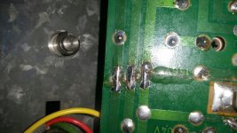
Some posts back I saw a PCB with a crack that looked like it would interrupt the traces as well. The proper way to mend a broken trace is to solder wire across it, or to run an insulated wire from the closest solder pads on either side. To mend a crack by soldering, you clean the surface of the trace in order to accept some solder. Apply a little solder flux (not plumbing flux, liquid electronic solder flux). Apply a little solder to each side, then "tin" (apply solder to a surface) a lead of solid wire, like a component lead you may have clipped off. Then, bridge the defect with the lead (hold with pliers or tweezers) and solder it to each side. I did not see that repair except on one trace. I think you used solder wick to cross the defect.
If a crack runs across a trace, assume the trace is broken. Even if it isn't now, it will probably fail later on in time.
-Chris
The steps you need to follow have been posted by Mooly and also myself. There may also be similar posts by other members trying to help you. Mooly brings experience to the table, so please review his earlier posts.
How much experience do you have working with meters and PCB boards, or electronics in general? We can not hand-hold you right down to probe placement for every step. We can help you with suggestions. You have to be able to understand what we are doing and be able to do some of the work by yourself.
Some posts back I saw a PCB with a crack that looked like it would interrupt the traces as well. The proper way to mend a broken trace is to solder wire across it, or to run an insulated wire from the closest solder pads on either side. To mend a crack by soldering, you clean the surface of the trace in order to accept some solder. Apply a little solder flux (not plumbing flux, liquid electronic solder flux). Apply a little solder to each side, then "tin" (apply solder to a surface) a lead of solid wire, like a component lead you may have clipped off. Then, bridge the defect with the lead (hold with pliers or tweezers) and solder it to each side. I did not see that repair except on one trace. I think you used solder wick to cross the defect.
If a crack runs across a trace, assume the trace is broken. Even if it isn't now, it will probably fail later on in time.
-Chris
Please advise me how could it be:
After the power on I have a good voltages on the caps. C2 is -22V and С3 is 20V. Motor is working. After the minute something happens and I have C2 -32V and C3 3V.
If the trace is broken why I have everything working at first minute? May be there is another explanation such a behaviour?
After the power on I have a good voltages on the caps. C2 is -22V and С3 is 20V. Motor is working. After the minute something happens and I have C2 -32V and C3 3V.
If the trace is broken why I have everything working at first minute? May be there is another explanation such a behaviour?
Nothing regulates the voltage on C3, the voltage just follows basic electronic theory.
When the voltage falls to 3 volts you must then check that the 14 volts AC is still present on the bridge. If it is then either the bridge is going open circuit or there is still a break you haven't found.
When the voltage falls to 3 volts you must then check that the 14 volts AC is still present on the bridge. If it is then either the bridge is going open circuit or there is still a break you haven't found.
I fitted a new bridge. Everything is the same. 14 volts AC is still present on the bridge. It's 100%. I realy don't understand how to fine a break. Everything seem to be ok.
Should I have a break to C3 or it could be anywhere on the PCB?
Should I have a break to C3 or it could be anywhere on the PCB?
You can find breaks by measuring for unwanted voltage across the print.
Look at the circuit...
When the unit goes faulty connect your meter (with it set to DC volts) and measure from C3 positive to the top connection of the bridge (top on the diagram). There should be zero voltage.
You can't have 14 volts AC applied to the bridge rectifier and only see 3 or 4 volts coming out on C3. Something is cracked or broken.
Hi terrom,
You can easily have intermittent connections with a cracked PCB. I would highly suspect this is the case. Note that intermittent connections can be highly sensitive to vibration or changes in position.
We have told you how to find a crack in a PCB a few times now. Please, go back and read this thread again. There was no need to replace that rectifier. Your fault could not have been that part. It sounds like you have problems on the circuit board.
I did see a crack in a PCB in one of your pictures. It looked like it was glued together, but there were not enough repairs made to the traces. If I were you, this is where I would start looking. Always assume there is a problem if you aren't certain about something you did.
Remember when I suggested that you only write down facts? In the last few posts you have made, you have jumped to conclusions without any factual evidence. You will not fix anything by doing that beyond pure luck and chance. Do yourself a favor and read this thread over carefully. Write down only what you have directly observed or tested to be a fact. Forget about everything else, just look at your list of facts. This way you will get somewhere.
Mooly and I are both very use to servicing equipment. We will go through some of your evidence in our heads, so it looks as though we are guessing - but we aren't. Those steps for you will be on your list, on paper. Please, give this a try.
-Chris
Could we put away this PCB? I couldn't find a problem. I have only 3V on the C3. I soldered all the cracks with the solder again but nothing changed. Let's put in aside.
I have a good but not cracked version of the second PCB with two bridges.
I removed R10 and R6 here and the bases of the AD149 transistors. The voltage comes up. What should I do next?
I have a good but not cracked version of the second PCB with two bridges.
I removed R10 and R6 here and the bases of the AD149 transistors. The voltage comes up. What should I do next?
What should I do next?
Honestly 🙂... you should persevere with the first board because it has such a basic and easily fixed fundamental fault.
You have 3 volts dc on C3 and yet you have 14-0-14 volts ac on the transformer and bridge.
It can only be...
1/ The bridge is faulty with the connection to both of the 'top' diodes open circuit.
2/ A break in the print from the bridge to C3 positive.
3/ A break in the print from C3 negative to the transformer centre tap.
If you had a short across C3 then the transformer voltage would be pulled down as well.
Perhaps you need to find someone local to you that can offer practical help.
Also wanted to answer: Could it be because of the faulty resistor in the theory?
I have this situation now:
1/ Put your meter on AC volts and connect the black lead to the junction of C2 and C3. That point is the also the middle wire of the transformer.
2/ Switch on and now read the AC voltage on the other two transformer wires at the point where they enter the bridge. - 16V AC on both wires
3/ Switch your meter to DC volts and keep the black lead on the junction of C2 and C3 as before.
Now measure the voltage to C3 positive end (should be around 21 volts DC) and also the voltage to C2 negative end (should be around minus 21 volts DC
I have +13V DC С3 and -22V DC C2
Last edited:
1/ Put your meter on AC volts and connect the black lead to the junction of C2 and C3. That point is the also the middle wire of the transformer. 16V AC
If you mean you can measure 16 volts AC between these points then there is a break ! Look at the circuit. C2/C3 junction connects back to the middle wire of the transformer.
Try and understand how it all works,
Bridge Rectifier Circuit :: Radio-Electronics.Com
Buck Converter Animation
Basic Rectifier Circuits
Bridge Rectifier Circuit :: Radio-Electronics.Com
Buck Converter Animation
Basic Rectifier Circuits
Hi terrom,
Keep on this board. You have just started to service it properly, forget everything you did before - especially anything you "know" to be true. That is one of your problems.
You could also have broken solder connections to components near where the board is cracked. Those trace repairs are good. To fix a broken solder joint, remove the old solder and make sure the lead isn't broken (it can happen where the lead breaks just above the solder surface in the PCB).
So, make sure you repair all the traces that could be broken first. Don't get ahead of yourself like you are doing.
-Chris
How about further along the crack on the board? You should also drill a round hole at the tip of the crack so it doesn't continue to grow.
- Status
- Not open for further replies.
- Home
- Source & Line
- Analogue Source
- Thorens 125 MK1. Help me please repair this PCB.