On the second 2bridges PCB version there R10 T6 T7 also isolated and there is voltage of 0.67V on ala the directions! while the other bridge give me perfect results like it's written on how to check the diode bridges.
Because you might be getting interaction from other parts and from residual voltage.
Its getting confusing when you keep mentioning the two boards because I don't know which one we are working on. So we are on the board with ONE bridge. Lets stay with that one.
Here is what you do.
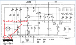
1/ Put your meter on AC volts and connect the black lead to the junction of C2 and C3. That point is the also the middle wire of the transformer.
2/ Switch on and now read the AC voltage on the other two transformer wires at the point where they enter the bridge.
Tell me what those two voltage are.
Its getting confusing when you keep mentioning the two boards because I don't know which one we are working on. So we are on the board with ONE bridge. Lets stay with that one.
Here is what you do.
1/ Put your meter on AC volts and connect the black lead to the junction of C2 and C3. That point is the also the middle wire of the transformer.
2/ Switch on and now read the AC voltage on the other two transformer wires at the point where they enter the bridge.
Tell me what those two voltage are.
Bridge is good. I changed it with the other one and have the same story.
When I checked it desoldered it gave me perfect results.
And the turntable works as it was. One minute of good working and then something happens and it goes to a broken stage with the same symptoms.
When I checked it desoldered it gave me perfect results.
And the turntable works as it was. One minute of good working and then something happens and it goes to a broken stage with the same symptoms.
1/ Put your meter on AC volts and connect the black lead to the junction of C2 and C3. That point is the also the middle wire of the transformer.
2/ Switch on and now read the AC voltage on the other two transformer wires at the point where they enter the bridge.
34V everywhere
2/ Switch on and now read the AC voltage on the other two transformer wires at the point where they enter the bridge.
34V everywhere
On the TWO bridge version it's
I removed R10 and R6.
1st bridge 10V AC
2nd bridge 18V AC
between the c2 c3 voltage is jumping very fast from 0 to 34V
I removed R10 and R6.
1st bridge 10V AC
2nd bridge 18V AC
between the c2 c3 voltage is jumping very fast from 0 to 34V
1/ Put your meter on AC volts and connect the black lead to the junction of C2 and C3. That point is the also the middle wire of the transformer.
2/ Switch on and now read the AC voltage on the other two transformer wires at the point where they enter the bridge.
34V everywhere
Lets concentrate on this one.
If you have 34 volts AC on each of the two transformer wires with respect to the centre wire... that is what you are saying... then you should be seeing 48 volts DC across C2 and 48 volts DC across C3 which is crazy 😉
I'm sorry
Everything is on the PCB ONEbridge version.
Wires from the transformer give me 16V each (it's jumping 15-16V)
bridge is working perfectly. What is next?
Everything is on the PCB ONEbridge version.
Wires from the transformer give me 16V each (it's jumping 15-16V)
bridge is working perfectly. What is next?
Last edited:
15 to 16 volts AC sounds OK for the transformer voltage.
Switch your meter to DC volts and keep the black lead on the junction of C2 and C3 as before.
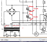
Now measure the voltage to C3 positive end (should be around 21 volts DC) and also the voltage to C2 negative end (should be around minus 21 volts DC)
Switch your meter to DC volts and keep the black lead on the junction of C2 and C3 as before.
Now measure the voltage to C3 positive end (should be around 21 volts DC) and also the voltage to C2 negative end (should be around minus 21 volts DC)
We (me 😀) are going to have to leave this for tonight but your reading of 13 volts is much to low. The minus 22 is good, the plus 13 is not.
A couple of things could cause that. The reading of 13 volts is like you would get if C3 was open circuit.
Switch it off and work carefully checking that the continuity of the print is good around C2 and C3. Make sure that the leads on C3 really do connect to the bridge and to the 'ground' centre rail. To be 100% sure measure from the leads on the cap itself to the board.
As additional confirmation make sure that C3 positive end (the lead on the cap)has continuity all the way to R9 and that C2 negative lead has continuity all the way to C9/R24 at the right of the diagram.
Yes 🙂 yes.
Last edited:
Your confusing me now 😀
I've edited the above post to make C2 read C3
Sorry... that's confusing for you.
I've edited the above post to make C2 read C3
Sorry... that's confusing for you.
As additional confirmation make sure that C3 positive end (the lead on the cap)has continuity all the way to R9 and that C2 negative lead has continuity all the way to C9/R24 at the right of the diagram.
Should I hear a "beep" sound on my multimeter if I put one lead to the "C3 positive end" and the other lead on the "R9 pot" on the pcb?
and
Should I hear a "beep" sound on my multimeter if I put one lead to the "C2 negative end" and the other lead on the "C9/R24 pot" on the pcb?
Hi terrom,
Most people get stuck by simple things. They make assumptions that a conclusion they made is a fact when it isn't true.
If you want to repair these, please follow some suggestions.
1.) Work on only one PCB at any one time. You start with one and continue until it is fixed.
2.) Get a pad and pen (not a pencil), you will write down facts and observations only.
3.) Under a bright light, examine the board carefully at different angles. Look for any hint of a crack or break in the board on both sides. Assume something is broken if you see a crack. Hoping for the best will never help you.
4.) To check for a broken trace. Start at a solder joint at one end, trace it to another end or ends. With your ohmmeter, measure from one end to the other or others at the solder pads. If your meter reads open, you have a break somewhere for certain.
5.) If you have done any work so far, assume you made a mistake and prove that you didn't to yourself. If there is a technical error, you very probably made it.
6.) If you pulled any parts to test, assume you installed them in the wrong position or in the wrong orientation. I always begin any job by taking pictures of how the components are installed before I touch anything.
To complete the setup on these turntables, you will need an oscilloscope in calibration. The turntable platter must be on for the motor to reliably turn smoothly. The belt as well. You align the motor settings with the turntable up on boxes so you can get underneath it. Be gentle with those controls. They are very old and are brittle now. The control positions should end up close to where you found them.
Read this thread again carefully. Read a post more than once to make certain you understand what is being asked or suggested. Also, read the manual over more than once to understand how to measure and what you are measuring. Do a careful check of the board first and assume you are seeing it for the very first time. Do not skip any steps if you figure you already did them. That is how you will become stuck again.
Do one step at a time, carefully, and make notes.
-Chris
You have got some good advice from anatech there 🙂
I'm sorry, I was going cross eyed keep looking at these diagrams last night and had the C2/C3 and R9/R10 mixed up.
Go back to your reading of 13 volts across C3. That is a wrong result and means either the cap is faulty or the connections to it are broken or there is some strange problem with the bridge.
You have 14-0-14 volts AC applied to the bridge. That must give you 21 volts DC across each cap.
C3 + have no connection to R9
I'm sorry, I was going cross eyed keep looking at these diagrams last night and had the C2/C3 and R9/R10 mixed up.
Go back to your reading of 13 volts across C3. That is a wrong result and means either the cap is faulty or the connections to it are broken or there is some strange problem with the bridge.
You have 14-0-14 volts AC applied to the bridge. That must give you 21 volts DC across each cap.
Attachments
Mooly what connections should be to c2 c3?
"C3 positive end" and the other lead on the "R9 pot?
"C2 negative end" and the other lead on the "C9/R24 pot"?
"C3 positive end" and the other lead on the "R9 pot?
"C2 negative end" and the other lead on the "C9/R24 pot"?
Look at the diagram above. You are trying to confirm (or not) that those four voltages are as marked. All can be measured with the black meter lead on C2/C3 junction.
This is to try and find why you have only 13v dc across C3 when it should be nearer 21 volts dc.
This is to try and find why you have only 13v dc across C3 when it should be nearer 21 volts dc.
Voltage to C3 positive end - 13V This voltage is wrong. We need to find out why
voltage to C2 negative end - minus 22V
- Status
- Not open for further replies.
- Home
- Source & Line
- Analogue Source
- Thorens 125 MK1. Help me please repair this PCB.