A bought a new 100pf cap and used it.
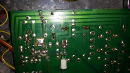
I don't know the story of the board but it was cracked and then glued by me. All the connections seem to be working.
everything was untouched including the R17 and R22
I replace all the ecaps: C2 C3 C4 C5 C6
I don't know the story of the board but it was cracked and then glued by me. All the connections seem to be working.
everything was untouched including the R17 and R22
I replace all the ecaps: C2 C3 C4 C5 C6
Something is unstable and I don't understand if it possible to find what is it. But it definately is a PCB
Also I tried to repair the same PCB but with the 2 bridges (see 1st page).
Here is another problem. All ecaps changed by me. Everything is also checked.
On this PCB the buld is not working and I have:
C2 - R9 - 166mV
C2 - R10 - 690mV
t4 B-E 0.44V
T4 B-C 0.31V
Bl motor pot - C2 - 0.19V
Bl motor pot - C3 - 0.19V
What is dead here?
Here is another problem. All ecaps changed by me. Everything is also checked.
On this PCB the buld is not working and I have:
C2 - R9 - 166mV
C2 - R10 - 690mV
t4 B-E 0.44V
T4 B-C 0.31V
Bl motor pot - C2 - 0.19V
Bl motor pot - C3 - 0.19V
What is dead here?
Cracked and glued 😉 Yep, that's hidden history all right 🙂
If you are sure the board is OK (check check and check again and also prod and poke the board to make sure there is no hidden crack or problem joint) then I would mark the position of the pots and try adjusting them slowly. You can always set them back to where they were if it makes no difference. Try adjusting R17 a little. Its possible the settings are motor dependent... different motor... different settings.
If that's no good and the problem is consistent, that is to say it works for a minute or so when cold and then goes faulty, then careful use of freezer spray might be useful.
Try adjusting first though. Alter the presets one at a time and slowly and see what they do.
Also I tried to repair the same PCB but with the 2 bridges (see 1st page).
Here is another problem. All ecaps changed by me. Everything is also checked.
On this PCB the buld is not working and I have:
C2 - R9 - 166mV
C2 - R10 - 690mV
t4 B-E 0.44V
T4 B-C 0.31V
Bl motor pot - C2 - 0.19V
Bl motor pot - C3 - 0.19V
What is dead here?
R10 should have the full supply voltage on it if its the same basic circuit as the one we are working to here.
So that fault sounds like broken print. Confirm the supply voltage is OK across C2 and C3 and then just trace the print to R10.
I checked everything many many times before I posted this thread. I soldered every possible problem. I don't know what to do now. It should work=(
Now I'm on the start with the first PCB. After the power on it gives me 0.6VAC to the motor and the bul lights too brightly. So it's not a C7 problem.
You need to concentrate on one board. Its too confusing to be talking about two faulty units at the same time.
The one we are talking about here in post #99
http://www.diyaudio.com/forums/anal...-help-me-please-repair-pcb-5.html#post4371999
Have you tried tweaking the pots ?
The one we are talking about here in post #99
http://www.diyaudio.com/forums/anal...-help-me-please-repair-pcb-5.html#post4371999
Have you tried tweaking the pots ?
I tried tweakin the pots. Nothing changed. I am at the start now again and have everythis that was when I strated this thread.
You say in post #99 that it now works for a little while before doing strange things. That gives you something to work to... is it temperature related, some part heating and breaking down. That is where freezer spray would be useful. Make sure there is no volt drop across sections of print as measured end to end with it all powered up and working. That might show a hidden break.
I'm sorry I've no magic answer 🙂 and its difficult without having the unit in front of me to get a feel for what its doing.
I'm sorry I've no magic answer 🙂 and its difficult without having the unit in front of me to get a feel for what its doing.
So
on the 1st PCB 1bridge version - problem unfindable at the moment
on the 2nd PCB 2bridge version - No voltage anywhere. On the bridge +- is 2,4V while on the 1st PCB 1bridge version is 30V. And the transformer gets hot very fast.
on the 1st PCB 1bridge version - problem unfindable at the moment
on the 2nd PCB 2bridge version - No voltage anywhere. On the bridge +- is 2,4V while on the 1st PCB 1bridge version is 30V. And the transformer gets hot very fast.
How should I check that there is no volt drop across sections of print? Where to put the leads?
Look at the picture in post #1
If you have no voltage on R10 then you should measure from its source at C3 and then go along the print all the way to R10. If there is no voltage on C3 then check the print back to the bridge and so on. If there is a break in the print then there will be a volt drop across it (like a broken wire).
If you have no voltage on R10 then you should measure from its source at C3 and then go along the print all the way to R10. If there is no voltage on C3 then check the print back to the bridge and so on. If there is a break in the print then there will be a volt drop across it (like a broken wire).
Regarding the 2nd PCB - there is no voltage anywhere (on the C3, R10, bridge) but If I remove the pcb anf check the transformer wires by the DVM it gives me 34V. How could it be possible?
It looks like you are getting some superb expert advice from Mooly here.
I don't want to knock you off track but here's my top tips:
I've got two TD125's and on both the PCB had hairline cracks which needed repairing. On one the crack was almost invisible and I only found it by checking for continuity with a multimeter. I had to replace the transistors on one also, they get rather hot and I don't think they're terribly reliable.
Also check and check again the contacts on the speed selector switch. I bit of deoxit would be good on these and while you're at it flush the fine speed adjuster through with contact cleaner.
Persevere, the TD125 is a superb turntable.
- Status
- Not open for further replies.
- Home
- Source & Line
- Analogue Source
- Thorens 125 MK1. Help me please repair this PCB.