Hi terrom,
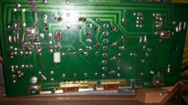
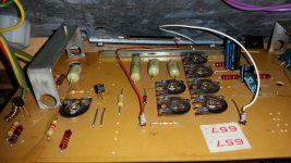
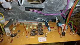
Can you take a picture of the area you worked in please? Both component and foil sides.
-Chris
Can you take a picture of the area you worked in please? Both component and foil sides.
-Chris
Are you absolutely sure that C3 is O.K.?
Disconnect T6 (AD149) and again measure voltage over C2 and C3.
Disconnect T6 (AD149) and again measure voltage over C2 and C3.
Hi terrom,
Can you clean the flux off that board so we can both really see it? Use lacquer thinners and a soft toothbrush. Make sure the fluid is away from the switch and any controls. Don't flood the board. The removal of the flux will allow you to actually see cracks or hair like shorts.\
-Chris
Can you clean the flux off that board so we can both really see it? Use lacquer thinners and a soft toothbrush. Make sure the fluid is away from the switch and any controls. Don't flood the board. The removal of the flux will allow you to actually see cracks or hair like shorts.\
-Chris
T6 is suspect. Also check T7.
Speed switch pads on the PCB need to be clean. Rubbing with contact cleaner or alcohol sometimes is not effective. Use a glass fibre brush with care. Also retension the sliding contacts of the switch.
Speed switch pads on the PCB need to be clean. Rubbing with contact cleaner or alcohol sometimes is not effective. Use a glass fibre brush with care. Also retension the sliding contacts of the switch.
Change the bridge. I'm assuming its not getting hot in all this.
Can you confirm the bridge (and anything else) isn't getting hot when the voltage on C3 is low ?
The only thing that is hot is the R10 resistor. I also think that a transformer should be coller. It's warm but in a working example it seem to be cooler.
Al also changed T6-T7 to another pair. Nothing has changed. Also removed the switch complitely. Have the same voltages.
T6 disconnected. Now C2 is 24V and C3 is 22V. Voltage is back!
We are going around in a circle here 🙂
Can you confirm the bridge (and anything else) isn't getting hot when the voltage on C3 is low ?
The only thing that is hot is the R10 resistor. I also think that a transformer should be coller. It's warm but in a working example it seem to be cooler.
Heat means that significant current is flowing.
I'm still puzzled by your readings around the bridge but lets move on from that. I think you mentioned earlier that the problem can be intermittent and that it works for a little while from cold. Maybe it was in one of its good moods 🙂 when some of the readings were taken.
Onward... lets look at this from another angle. If R10 is hot then it means that T6 is conducting heavily.
Where is that current going ? Well it can only be into the motor. There is no other low resistance path available to it.
Have we proved the motor good, and that its not sticky or tight to turn ?
If you turn it by hand, does the voltage change on C3 ?
----------------------------------------------------------------------------------------
What has to happen for T6 to be on...
For T6 to be on (and so R10 to be hot) there must be at least 0.2 volts or so across R6. Its 0.2 because the AD149 is germanium and these have a lower forward voltage than all the other transistors.
Check it.
For R6 to have 0.2 volts across it, T1 must be on. That means around 0.7 volts will be across the base/emitter junction of T1. The base would be the most positive with respect to the emitter.
Check it.
For T1 to be on, T3 must also be on. That means around 0.7 volts across the base/emitter junction of T1. This time the emitter would be the more positive than the base.
Check it.
----------------------------------------------------------------------------------------
If all those conditions are met then it suggests that the circuit is 'stuck' in a non oscillating state.
We all want you to fix this you know 🙂
and now It don't work at the start every time I power it on. I couldn't back to the moments whet it's working for a minute!
Its always better to try and find a fault by other means but as long as you have the correct transistors and fit them correctly it would be 100% conclusive. It would either fix it or not.
(Refresh the page because I added a bit more info to the post above)
(Refresh the page because I added a bit more info to the post above)
If you turn it by hand, does the voltage change on C3 ?
no changes in voltage after my rotation of the motor
Hi terrom,
Put the transistors back where they were. You can test them with a transistor checker to make certain you aren't creating another problem.
Answer Mooly's last post in order and do not jump ahead. Ever notice that everything goes sideways when you do these things? I have.
The main test result is not if the motor turns, you are being asked for some specific readings. You need to do these things in order and resist trying anything else on your own. We can't help you if you continue to go off on your own - without addressing questions that are important.
So, right now STOP! Test the parts you pulled. Reinstall the parts you pulled. Carefully examine your work, clean the solder flux off before you examine your work. After all that, follow Mooly's post and answer only those questions. We can get into anything else after the questions are answered.
By going off to do your own thing you are making it impossible to help you.
-Chris
- Status
- Not open for further replies.
- Home
- Source & Line
- Analogue Source
- Thorens 125 MK1. Help me please repair this PCB.