Chris, I don't understand. I've just answered the Mooly's questions.
Just don't have a hard brush to clean the flux now. But this flux is from Thorens not mine.
Just don't have a hard brush to clean the flux now. But this flux is from Thorens not mine.
When the power is off, and you rotate the motor by hand, this must go effortless. If it takes some force to turn the motor, this is the first thing to take care of.
But earlier you said that with a third board this turntable was working?
So, motor O.K.???
But earlier you said that with a third board this turntable was working?
So, motor O.K.???
When the power is off, and you rotate the motor by hand, this must go effortless. If it takes some force to turn the motor, this is the first thing to take care of.
But earlier you said that with a third board this turntable was working?
So, motor O.K.???
The motor is a so called PM (permanent magnetmotor) with 16 poles when you turn the pulley its feels its going in little steps , thats normal !
Hi terrom,
I must have been posting while you were answering Mooly. Please disregard my comments about answering Mooly's questions. But you still can't suddenly move ahead on your own. Troubleshooting is a step by step process where we only change one variable at a time to avoid getting into situations where too much changes at one point in time.
It is very important that you do exactly as requested when someone else is trying to help you. When you take a step, exchange one part at a time and test before doing anything else. Replacing 4 (for example) transistors in one step is not one step, it is four steps without testing in between. This makes the troubleshooting step next to useless except that doing this can easily make you follow the wrong path.
So, step by step means to try one thing and observe any changes in operation or measurements.
-Chris
To confirm it I've just tried another motor. Result is the same. 22V + 13V with the motor bit it was 22V + 22V without the motor on C2 C3 and the bridge
Hi terrom,
Your second link doesn't work for me.
It looks like you might have a crack on a trace to the left of the light bulb. Nice job of cleaning up the flux. Now you can really see your connections. It is important to clean these things up since otherwise you can't inspect your own work. You would never see a small solder bridge under the flux.
-Chris
across R6 is 0,7V DC, R7 - 1V DC
0.7v means T6 is fully on. I actually suggested it would be around 0.2 volts but of course the volt drop across R10 is adding to the base/emitter drop of T6.
across the base/emitter junction of T1 minus 0.7V
If the red meter lead was on the base and the black on the emitter then yes, that is also fully on.
across the base/emitter junction of T3 0.65V
Again, that suggests it is on.
Motor is very hard to turn but it's not rotating
Yes when it's powered off the motor is very freely.
And Everything worked with the other PCB.
The motor is hard to turn when powered up because of the continuous DC current flowing within it.
----------------------------------------------------------------------------------------
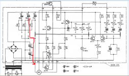
I want you to look at the circuit and put the speed switch to the middle position. Now put your meter on DC volts and measure from the negative end of C5 to what is the left hand connection to the motor on the diagram. There should be zero volts. This is to test for continuity through the switch.
----------------------------------------------------------------------------------------
Look at the circuit again.
This time switch it off and put your meter on ohms (to check continuity). Connect the meter between T5 base and the end of C10 that goes to the switch. It should read 'short circuit' or very nearly zero ohms. This is to test for continuity through the other section the switch.
Now put your meter on DC volts and measure from the negative end of C5 to what is the left hand connection to the motor on the diagram.
I have 9V DC. One lead to the C5 minus and the other to the motor as rugular?
to the RT point (red wwire of the motor) is 0V
I have 9V DC. One lead to the C5 minus and the other to the motor as rugular?
to the RT point (red wwire of the motor) is 0V
Last edited:
This time switch it off and put your meter on ohms (to check continuity). Connect the meter between T5 base and the end of C10 that goes to the switch. It should read 'short circuit' or very nearly zero ohms. This is to test for continuity through the other section the switch.
It gives me 0.3Ohm and I have a beep sound so it have connection T5 base - C10
It gives me 0.3Ohm and I have a beep sound so it have connection T5 base - C10
I have 9V DC. One lead to the C5 minus and the other to the motor as rugular?
to the RT point (red wwire of the motor) is 0V
That needs looking at closely. With the switch in the middle position these points should be linked (if the diagram is correct)
Attachments
So its OK.
Just a slightly crazy thought. Is the bulb permanently lit ?
(I've never worked on one of these boards but I have had small bulbs go intermittent before now. If there is a break in the filament it can keep making and breaking connection)
Just a slightly crazy thought. Is the bulb permanently lit ?
(I've never worked on one of these boards but I have had small bulbs go intermittent before now. If there is a break in the filament it can keep making and breaking connection)
I'll have to give it more thought because its defying our best efforts at the moment.
The whole circuit is really just an amplifier with a long tailed pair at the input (T1/T2) and so we should be able to at least test it at a DC level............. I'll see what I can come up with tomorrow.
In the meantime just make sure there are no breaks around T1/T2. Use the circuit and measure DC voltage between the various points.
For example T3 base connects to T5 collector and so there should be zero volts between those points. T3 collector to R12 is another check. The same for T4 base and its connection to the bulb... and so on.
Reading back on the thread and it 'worked' when we did some work around C7.
Its not over yet 😉
- Status
- Not open for further replies.
- Home
- Source & Line
- Analogue Source
- Thorens 125 MK1. Help me please repair this PCB.