Yes.... errors....have to check step by step
painting all the schematic lines into a printed copy...observe lines if they are in place and paint the schematic in red...check all transistors position, and remove them to test out from the circuit..you have errors.
Sorry.... the debugging only you can make..i cannot discover what is going wrong from Brasil..i wish i could..but it is not possible.
regards,
Carlos
The DHR Turbo is a super stable amplifier
Here you listen the unit playing with plus and minus 20 volts.
It was designed to use 63 volts..... you see how stable it is...one third the voltage and still working fine.
This audio has good quality, despite beeing recorded using the digital camera microphone, you can listen quality..imagine that quality listening alive..say...no digital camera recording.... say..you listen to it.
Use a good amplifier and good speaker to listen..the PC small speaker cannot reproduce the deep bass present into the recording... about the high end...maybe..but better to use good audio equipment when go evaluating performance..those cheap (chip) PC speakers are not good enougth..even the best brands are not..the ones i could listen were just reasonable... if you have not a miracle one, say, a miraculous unit, then plug your main amplifier into the computer.
Enjoy Dx amplifiers..all them tuned to performance to your happyness..and this is guaranteed!
http://www.youtube.com/watch?v=QaYGJWkuhBg&feature=related
regards,
Carlos
i dnt know whats happened but i have made thinsg worser even though this time i triple checked evrything now it seems am getting only 2.5 v at rails and leds are not powering up and bulb at the main lights up i beleive it is the transistors this time.
damn it a disaster for me i woke up at 5 am to start the project and clean up tracks and check evrything. it 7pm now.
i think the transisters are dead now due to sodlering at high temperature looks like i have re-check them again.
damn it a disaster for me i woke up at 5 am to start the project and clean up tracks and check evrything. it 7pm now.
i think the transisters are dead now due to sodlering at high temperature looks like i have re-check them again.
right found the problem miswired transister but back to prevoius stage were i only get low faint sound if i touch the bias trimpot wire with finger to heatsink.
any body willing to take on this project for me i will give them money or transformer and some 2sa1943/5200 transisters 6 of them or gainclone amp board with chips or dhr turbo board this board cost me approximately 50pound for two and are industry standrad.
all you have to do is make the damn thing work and ship back to me.
all you have to do is make the damn thing work and ship back to me.
Take a good rest...you will find the errors
If you touch the bias with your finger and are listening something..this means things are not very good, as the output has not all that sensitivity.... you input differential may have mistakes too as you have not signal there.
Mistakes are very normal...people use to find them in a matter of hours..others take days and some weeks..others give up...well.... everything is solution...also in the war you can attack and go backwards..to retire...this is also a solution..sometimes to go back is needed to have more strength to attack once again.
But, if someone wants to help you.. and can help you...and lives in your country (turn things easier to use Fedex).... it is a good idea to, as you are already tired.
The amplifier is not a damn thing.... several were assembled..but errors happens usually.
good luck,
regards,
Carlos
Yes ... i understood that .... damn thing you have made
I could understand what you meant... and trying to give you courage to continue...but take some time and some good breath of fresh air..put the damn thing into the closed and go to do other things..just forget for a while..take a good rest.....we all have those problems, not only your, not your special condition...it is normal to make several mistakes..and to do them in a repeated way, and daily.
Sometimes the input is shorted..reason why audio is not amplified and we go searching for other things for hours long, when we just have forgoten, the short we have made previously to adjust the amplifier...i did that several times.
This is all normal...also to call the amplifier damn thing.
Joing the club man... and feel youself very welcome.
And be happy..no one here is better or worse than you are... watch the picture..each point of ligth is a big town, with several millions, all them making a lot of daily mistakes.... you're not the only one brother!
Some of them are pride and arrogant, and will never admit they make mistakes..but i guarantee they make..the biggest one they're making rigth now..saying (or thinking) they do not make mistakes.
You not a looser because of those things you're living..in my point of view you're a winner, as you have courage to say.... this is character!... a real man!
regards,
Carlos
URL=http://img22.imageshack.us/i/worldatnigth.gif/]
An externally hosted image should be here but it was not working when we last tested it.
[/URL]messing ariound with amp i come to conclusion errors must be 63v 100nf that joins to 220 ohms looking at alex mm board which mine is exact replicate of his. he uses .1m dnt knw the voltage i think this affects the amp input signal as you said area error must be in diffrential and the bias trim pot i just touch the leads on it and touch the heatsink i can faint music. other than that i dont know i checked all components.
right i checked all the componets on the board chnaged the pre drivers and other transisters excpet the toshiba 2sa transisters . i only get sound by touching the trimpot wire and touching the heatsink of course the sound is very low about 1 watt but i can hear it.
could this be related to output toshiba 2sa transistors.????
could this be related to output toshiba 2sa transistors.????
Check also the VBE multiplier board.... if you have external bias control
I do not think the Toshibas, even fake, can do that.
Measure all voltages from base to emitter and inform...maybe we gonna see where you have troubles.
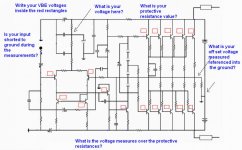
inform each transistor base to emitter voltage.
It is normal to give a check, a double check and even a tripple check and not observe an inverted transistor.... happens a lot..if your amplifier is not working..for sure, absolutelly sure, there are errors.
regards,
Carlos
I do not think the Toshibas, even fake, can do that.
Measure all voltages from base to emitter and inform...maybe we gonna see where you have troubles.
inform each transistor base to emitter voltage.
It is normal to give a check, a double check and even a tripple check and not observe an inverted transistor.... happens a lot..if your amplifier is not working..for sure, absolutelly sure, there are errors.
regards,
Carlos
the only reisister i have measured that seems to be giving odd reading (board taken out without connected to output transistor) is the 2.2ohm reistor that connects to transistors wire leg. this reading is 2.6ohms and 2.7ohm on some resistors(llabeled 2.2 ohm).
i got a weird feeling that it them reisstors or zener diode or the vas transistor and the other two small tranistors(1837 etc).
i think output are real.
once assembled back i make a video of the amp and show you on youtube for observing but evrything seems fine accorindg to circuit diagram must be fake parts or i have used parts such as polyester with high voltage/ high nf rather the ones shown in the circuit but these were used from your advice in the prevoius discussion on the forum.
Better to produce high resolution pictures
Natural ligth, crispy focus using macro function and small tripod, air view, no flash, upper view and under board view without too much shadows.... this help us to inspect.
VBE measurements help us to identify failures, wrong connections, missed connections and shorts.
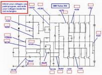
Voltage chart was published... certainly it was, so, compare your voltages with the ones published and inform your readed voltages written above the ones informed... this will help us to see were we may have errors.
Without the needed tools to debugging, the printed schematic with the copper lines painted (red) to be sure all connections were made.
Without all transistor removal and off board testing
Without check all voltages and VBEs.
Without check with the board layout producer if something need to be cutted or jumped.... without all that stuff you gonna be alike a blind man in the middle of the crossfire of shooting.
Use all the methods of debbuging and read all thread, follow instructions and obbey whole basic traditional debugging method, or you will be wasting your time and mine too.
There's no magic discovery.... try and error and visual inspection fails and takes too much time and creates frustration.... the voltages, as referenced, were provided into this same thread first page.
Here you have, published, the voltage chart..use it.
Youtube, for debugging, is a big waste of time...youtube serves only for presentation, teaching, for fun, for some non very good sound quality evaluation ... serves also for advertising and never for debugging.
I will be able to help you, ONLY, if you follow my instructions...i want to see the schematic with the line painted on red, to be sure you have checked as i have asked you to do..and them the voltage chart you will measure into your assembled board..also the VBE chart...also the clear report you have measure all transistors outside the board...non connected ones.
regards,
Carlos
Natural ligth, crispy focus using macro function and small tripod, air view, no flash, upper view and under board view without too much shadows.... this help us to inspect.
VBE measurements help us to identify failures, wrong connections, missed connections and shorts.
Voltage chart was published... certainly it was, so, compare your voltages with the ones published and inform your readed voltages written above the ones informed... this will help us to see were we may have errors.
Without the needed tools to debugging, the printed schematic with the copper lines painted (red) to be sure all connections were made.
Without all transistor removal and off board testing
Without check all voltages and VBEs.
Without check with the board layout producer if something need to be cutted or jumped.... without all that stuff you gonna be alike a blind man in the middle of the crossfire of shooting.
Use all the methods of debbuging and read all thread, follow instructions and obbey whole basic traditional debugging method, or you will be wasting your time and mine too.
There's no magic discovery.... try and error and visual inspection fails and takes too much time and creates frustration.... the voltages, as referenced, were provided into this same thread first page.
Here you have, published, the voltage chart..use it.
Youtube, for debugging, is a big waste of time...youtube serves only for presentation, teaching, for fun, for some non very good sound quality evaluation ... serves also for advertising and never for debugging.
I will be able to help you, ONLY, if you follow my instructions...i want to see the schematic with the line painted on red, to be sure you have checked as i have asked you to do..and them the voltage chart you will measure into your assembled board..also the VBE chart...also the clear report you have measure all transistors outside the board...non connected ones.
regards,
Carlos
Attachments
Inform the needed voltages..here you
have the image to you.... them open it, push the button you have above the Ctrl..keep it pushed and them push the Print screen button.....and them open your paint program and paste the image into the paint program screen...now you can type the values on it.
Save it and them crop and copy to GIF or JPEG and publish the image this will make us able to help you.
regards,
Carlos
Attachments
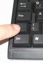
This button, pressed together the Print Screen
will send your image to the transference area memory (copy)..then you will be able to transfer the image to the paint program to write informs on it.
I think you may know that stuff...i am informing "just in case...."
regards,
Carlos
will send your image to the transference area memory (copy)..then you will be able to transfer the image to the paint program to write informs on it.
I think you may know that stuff...i am informing "just in case...."
regards,
Carlos
Attachments
To help people to inspect boards, we need to have the board layout used as reference
and a very good picture...NOT that awfull thing i am showing you.
this one i am showing is "air view"..or upper view as i told.... other good thing is that it is filling almost the entire frame... focus here is not so bad..... but.... has shadows and brigth.... we cannot have brigth spots (this board has not too much) and we cannot have shadows...we must be able to read the transistor numbers and resistance values, and to inspect details, so..image need to have a couple of megapixels (at least 3 Megabytes).
Camera need a tripod....also the macro function..to disable the flash and to use natural sunligth with the use of white paper or styrofoam boards to reflect ligth into the object you will photograph to dilute shadows and to fill all spaces with difuse ligth.
Here, and example of image that may be good to show a board..but never as image to be used to debugging, to the search of errors.
Cell phone cameras serves to the manufacturers only.... awfull images, only for marketing purposes... serves for nothing in electronics.
regards,
Carlos
An externally hosted image should be here but it was not working when we last tested it.
1. input is shorted
2.output wire to ground wire is 320 mv
3.my protective load resistance is 10 k 10 watt
4.voltage measured over protective resistances are 25 volt over the negative resistance rail and for positive rail is 25v as well but the ground is connected to earth and output ground as well.
5.offsett voltage is with ground attached to earth is 5.5 volt and even with ground wire is removed it is 5.5 volt.
6.base to emitter with input shorted is 407mv for all transistor on the negative side of the board.
Now for the positive side of the board with input shorted are: also 407 mv
My power supply measured over the caps is dc volt of (negative of cap and positive of cap measured = 62.8volt.
images will uploaded in few hours just getting camera charged up.
The series resistance cannot be 10K...this is too much
100 ohms is the maximum value.... a good value is 10 ohms as easy to divide without calculator using the "ten" base.
If you have 25 volts over the resistance...this means the current crossing is 2.5 miliamperes, and this current is 40 times smaller than the needed.... also the resistance used is 100 times the biggest value to be used.
Also, when you have 25 volts losses into the protective resistance, you will have only a few volts to feed the circuit...and this voltage is not enougth to power transistors on.. they are cutted, not conducting, not working Joka22.
Man!... really!...if you have used 10K ohms resistance as protective..not a typping error, you have a lot of courage to build an amplifier, as your knowledge seems not to be enougth to do that.... i am not happy to say..but i have to do that.... i am afraid your chances to suceed are not so big.
Also this is not an amplifier to beginners.... it has power, and some skill is needed...no one can inject that into your brain so fast as you need to succeed...i hope to be wrong and your carefull construction results in nice operation...but i am afraid the result can be different.
Reduce the protective resistances to 10 ohms, or 12 ohms, or 15 ohms, or 22 ohms, or 27 ohms, or 33 ohms , or 47 ohms, or 56 ohms, or 68 ohms, or 75 ohms, 82 ohms or maximum of 100 ohms to 10 watts (minimum power..if bigger, the better)
Maybe you have not a problem..maybe only that 10K is the problem... this VBE shows the transistors are not biased correctly, they are cutted, not conduction, they are "off".
Posting the "bad image" example once again..some bug happened with the imageshack
regards,
Carlos
An externally hosted image should be here but it was not working when we last tested it.
- Status
- Not open for further replies.
- Home
- Amplifiers
- Solid State
- This is the DHR.... Dx High Resolution Turbo