Ajpl66, awsome picture quality and lovely boards you have made
They seem to be to the DHR Turbo.
Thank you by the preference and confidence into the amplifier circuitry..
Works fine, reliable and strong...i do use this one in my home, because it is my daugther's prefered one (teenager wants punch)
I would like to welcome you to the crew and to thanks Alexmm by the kindness to provide us board"s layout.
Alexmm is a very important support the Corporation, as also Todd Johnson with schematics and Greg Ersine with logistics.
Thanks Hugh Dean by the inspiration and some hard work, now we have a reliable amplifier ready to punch enormous ammount of power into all nigth ball
regards,
Carlos
......................................................
I would be happy to receive, from you, pictures doing your progression building, in special because,you have produced the best board picture till our days...excelent photographer and wonderfull equipment (as also very pretty boards)
Deep congratulations man!
.....................................................
An externally hosted image should be here but it was not working when we last tested it.
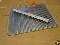
LOLZ those pcb boards shown approximtely three or four threads above from this thread i had them made from some guy on ebay £50 odd pounds expensive but qulaity industry standard and very thick trust me the boards get very heavy when populated so pcb must be thick .
any way guys i finally got my heatsink yep long exuasting wait but well worth it all for £29.50 won it today on ebay.
any way guys i finally got my heatsink yep long exuasting wait but well worth it all for £29.50 won it today on ebay.
Attachments
Thank you to let us know you have made that
We will be monitoring your progress.
Keep us informed.... let me know all you procedure steps... having pictures post them.
regards,
Carlos
We will be monitoring your progress.
Keep us informed.... let me know all you procedure steps... having pictures post them.
regards,
Carlos
Spare DHR TURBO PCB FOR SALE
I have one spare channel pcb for dhr turbo if anyone is interested to buy as i need money to buy the bloody thermal compound and those transparent mica washer for my toshibas transistors.
£20 pound for the pcb including delivered to your door. has one 4r7 ohm 3 watt resistor sodlered on will show picture of board later on. decided to make one channel as it has enough power for my needs so this second board is surplus to my needs.
(No photoresist just high class industry standard pcb board finished in roller-tin and pre-drilled).
soprry about my late reply carlos i will upload picture of the dhr turbo when inserted to heatsink but i will still require help this bias and dc offset formula kinda scared of doing this procedure as i dnt knw what to expect tried finding videos on solid state bias tuning and offset but only find valve type and they not prper instructions for newbie like me. things like emitter reisstor and all that audio language slang term is kind confusing i need a video actual showing dhr turbo getting bias tuned and offset and how to work out the formula.
Sorry, i cannot upload so big video to youtube
then use the informs you have here, into the Dx Amplifier section you have the adjustments steps and a chart...that chart explains everything.
http://users.tpg.com.au/users/gerskine/dxamp/
To the DHR Turbo, the difference you may have is that you will have to measure around 1 milivolts (adjusting bias) over the emitter resistances ... this is to check if all them are conducting.
regards,
Carlos
Attachments

This stuff was explainded, several times, into the Dx Amplifier thread, also the HRII
group buy..also into the Dx Precision 1.... the procedure is the same for every amplifier.
Into the Dx amplifier, Greg pages, you have the instructions you can apply to all wide world amplifiers.... the method to measure current over a protective resistance serves to all amplifiers..also the off set measuring system and the check up over emitter resistances into the output.
Take some time to read....this will be very helpfull to you... will save money, as errors may kill transistors.
Off set can go to 25 milivolts...better to adjust bellow 5 milivolts if possible (depends on transistor matching)
Bias can be adjusted from 50 to 100 miliamperes to each rail...positive rail may have 8 miliamperes more..no problems about that..this is normal.
Voltage measured over power transistors emitter resistance must be 1 milivolt of less than that..but you must be SURE, that all transistors are conducting..and they are conducting when you can measure something into the emitter resistances..when electrons flows througth a resistance, a voltage is developed into this same resistance extreme..potencial difference..electrons difference..electronic difference that in other words means "voltage"
regards,
Carlos
An externally hosted image should be here but it was not working when we last tested it.

ok numbers are going down
ha ha ha uncle charly
happy birthday ...all the best for you and family ....many many years to come many amplifiers to come ....and never mind .... be proud and happy !!!!
ha ha ha uncle charly
happy birthday ...all the best for you and family ....many many years to come many amplifiers to come ....and never mind .... be proud and happy !!!!
Thank you my dear friends Dudainc, TAJ and Sakis
I am glad you have remember that.
Great....now i am a powerfull man... alike a muscle car... a 5.8 litters engine...with double compressor, 4 valves each cilinder, V12 machine... dry carter... rounded piston head and Hemi chamber... multipoint fuel injection and flex fuel.
Yeeeesssss!
Carlos
I am glad you have remember that.
Great....now i am a powerfull man... alike a muscle car... a 5.8 litters engine...with double compressor, 4 valves each cilinder, V12 machine... dry carter... rounded piston head and Hemi chamber... multipoint fuel injection and flex fuel.
Yeeeesssss!
Carlos
okay carlos i kinda erm understand it but we have one bias pot to tune the rails so i can tune both rails from the bias pot right.
what if one rail is alot larger in current than the other one how would i tune that one when i have one bias pot. (yes i know your thinking "joka dummy").
The reason i say this we using two multimeters to measure millamps on neg and postive rail wouldnt they be the same if so why not use one multimeter to measure bias on one rail since they be same current and we have one bias pot.
Yes, one pot adjust bias to both amplifier rails
The need to monitor both rails is done, usually, to detect if something goes wrong as this uses to appear to you as an enormous consumption, or no consumption to one rail..... or the current appear larger than the other... and this can be really larger....sometimes 20 times different or something alike.
We can use a single multimeter.... doing the measurement twice..first you check positive rail and them you jump to the negative rail...the problem on that method is heat, as you can measure positive rail first and the current there can be fine while the other rail can have enormous consumption burning the protective resistance or some amplifier component due to mistakes made during the amplifier construction.
Mistake happens!.... and happens usually, happens daily, and happens continuously... and happens also with deeply skilled folks.... we humans... we use to make mistakes everyday, and sometimes several mistakes each day...judgement errors, motion errors that result some toe damage..cutting ourselves shaving.... and several wrong conclusions about other people behavior...other people reasons to do this or that is an example.... one of our biggest mistakes is the arrogance to think we do not make mistakes..this is the biggest one..the arrogance..and is, by itself, the first and main human mistake.
Someone, can leave the house with a big and heavy luggage, a strong bag..and that seems very heavy...seems heavy enouth to carry a children inside....many travells to the car..and them the guy return with the same bad empty .. you perceive by his movement the metalic bag is ligth and empty...once again he goes out with that heavy bag once again.... the bag goes to the car..then he goes away and returns one hour passed by with an empty bag once again...and the guy wife has disappeared... a long time you do not see her...you may think the woman is in pieces inside that bag...but in the reality the man is carrying Cristal pieces to another appartment..he may just be moving and doing that part of the moving personally to avoid broke cristal glasses...wife can be sleeping, a little bit sick...we analise things wrongly (movie restoration - 1954 - in the movie case..inside the bad was really his wife... Grace Kelly was the main actress).
We do those things, and into audio electronics, this always results showing you enormous off set and unballances into the rail currents.... this is what results when we make mistakes into amplifiers.... we do not adjust only to keep the standards, but also, and much more important, to check if everything is in order.
Into amplifiers, a low offset, and the same bias (almost) comparing positive rail to negative rail shows you the amplifier, as a system, is working fine...another test is to measure all VBEs.... and they must be simetrical in value refered to the rails (PNPs and NPNs counterparts) and must be higher than 500 milivolts and lower then 650 milivolts if your amplifier is working into class AB.
Another test is to measure temperature during stand by mode....during iddle the temperature cannot be too much bigger than the environment temperature if you just switch your amplifier "on" seconds before you start to monitor the unit's temperature, then you will measure some degrees above environment temperature... a couple of degrées..maybe 5 degrees above environment.... and this after several minutes after you turn on (without reproduce audio, no power..idle..stand by mode..no signal mode)...and when working full undistorted power... after several minutes, cannot be higher than 52 degrées celsius or you will loose transistors very soon...they will burn... the high temperature means something is wrong.
High temperature also shows you that your amplifier is oscilating ...when oscilating you will have enormous power consumption, even iddle and will have as a consequence high temperature mainly into the output transistors and/or drivers...this will also show you how good and big are your heatsinks.
Oscilations appear into the output when no sign is entering and you are able to measure AC volts into the output... from output to ground of course.... no sound appear into the speaker, as oscilations use to be into high frequencies and we are not able to listen.
Another test is to put you finger into the input..our body behaves alike an antenna, an aerial and we receive electromagnetic waves that comes from our house AC mains wiring... so...we are a 60 hertz "generator"...or we can behave this way.... inserting your finger into the amplifier input terminal you may listen a perfect sinus tone...and output voltage use to be high, but never the maximum output voltage (RMS)..it uses to be from 5 to 15 volts when your power amplifier sensitivity was adjusted correctly (the feedback gain resistance adjusts that... reducing it the sensitivity increases... increasing it the sensitivity decreases....the one has a condenser in series that goes to the lifted input).....if you listen broadcasting and other noises than a pure low frequency tone..then your amplifier is not very stable... something is wrong with the board, or the lag compensation capacitor..or you forgot your zobel filter...or the feedback line capacitor was missed (the one is in parallel with a resistance that is connected from the output line to the feedback differential transistor base..the rigth side one...the second one into the feedback pair)...or your speaker passive crossover is a crazy one that has big capacitance between the speaker terminals.
I do not think Joka is dummy, but i think you have too much courage to assemble such big amplifier having not that enormous know how...well.... courage is important and i value that..but you may keep a fire extinguisher near you my dear.... ship happens!
regards,
Carlos
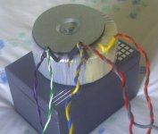
antrim toriod wiring scheme help needed
Hi i have a very heavy large antrim toriod with
two secondary wires blue,red,yellow,grey.
primary wires are orange, brown
but what are the extra wires which are:
black,purple, green, white
i like in uk 240 volt and i would like to use one bridge rectfier for the dhr turbo but the wiring scheme does not exactly match the antrim website wiring scheme.
if anyone knows how to wire this toriod for use with one bridge rectifer to dhr turbo (iwas thinking using one secondary (43vac) wiring to power the dhr turbo and the other secondary just insulated not used.
Attachments

Hi,
check the continuity through each of the twisted pairs.
This confirms they are the same winding.
Check there is no continuity between any one pair to any other pair.
This checks you have /have not got tapped windings.
Measure the resistance of each winding.
Post all your results.
Before you plug anything into the mains, get an insulated terminal strip and secure each wire end into a separate terminal.
Have that bulb tester assembled and ready to use. Build the simple one first without any switches.
okay for the secondary wires grey and blue conduct and the meter makes the sound and same for red and yellow. resistance over the same wires is (0.9ohm).
for primary leads brown and orange thier were no continiuity and no ohms reads zero.
okay purple and green read 1.3 ohm and does conduct on the continiuity test.
and for the black wire does not show ohm it is zero and does not conduct on the continiuity when joined to the white wire or green (white and green are joined together with spade crimp.).
all the wires that do show continiuity and ohms come from the same plastic sheating from the toriod. plastic sheating - the round black insulater from the actual toriod.
excpet the yelow sheating that is the primary wires they do not conduct or show ohms.
excpet the yelow sheating that is the primary wires they do not conduct or show ohms.
- Status
- Not open for further replies.
- Home
- Amplifiers
- Solid State
- This is the DHR.... Dx High Resolution Turbo