Those resistances works in parallel... the supply see 0.2 ohms to each rail
and this is the resistance you may have in series with the positive half cicle.... also you gonna see 0.2 ohms in series with the negative half cicle...... this is what the load (speaker) will "see"... will have to receive the alternated signal (audio).
This is the same sittuation you may have using a single output pair to an amplifier... and using 0.2 ohms resistance into the emitters...... the idea is to provide to each transistor a good way to control power and to equalize power into all of them.
Also... it is an interesting use, as you can use non inductive resistances, easy to find into 1 ohms value and able to hold 3 to 5 watts each one of them.
DHR Turbo – revision 2... supply 70 plus 70 Vdc
Power RMS Rail current Total current. Impedance
610W 7.9A 15.8A 2 ohms
620W 6.5A 13.0A 3 ohms
485W 5.0A 10.0A 4 ohms
405W 4.0A 8.0A 5 ohms
340W 3.4A 6.8A 6 ohms
290W 2.9A 5.8A 7 ohms
270W 2.6A 5.2A 8 ohms
Input signal sinusoidal into 1Khz… continuous power into
The threshold of clipping.
A dream amplifier to powerholic monsters!.... it is huge, reliable, stable into temperature, low cost amplifier, simple to build, not fashion parts, excelent sound, can reproduce 1 Hertz full power...can go over 100 Kilohertz without distort or change waveform.
The power can be much bigger than the one informed...this is the guaranteed clean power (unclipped)...but as humans tollerate clipping, you can double that without any fear to be telling untrue stories to folks.
regards,
Carlos
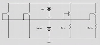
Power equalization.... equal power to transistors
Emitter resistances equalizes (turns equal, turns the same) the power into transistors... almost the same.... reduces differences.
What differences?
Each transistor has it's own gain, if not from the same "waffer" into the production, they will be different in many things..in special the gain will be different...and this creates problems.
The one that has more gain will work more than the other... it will hold more heat than another one...this will mean it can burn and the other will not burn..one will work too much and the other will work less.
Observe, watch my sketch.... see that we have two transistors into the left side and two transistors into the rigth side...imagine they are into different amplifiers.... those two into the left have not equalization resistances into the emitters... the other two at rigth side have equalization resistances into the emitters.
I will force them to conduct...will use a battery that will send them 800 milivolts of continuous voltage into the base...this will circulate from the base to the emitter and will turn those transistors on..... as a consequence current will flow from colector to emitter... and the current will be different...because those transistors have HUGE DIFFERENCES OF GAIN.
The 12 volts battery will power the colector to emitter circuit.
Observe the schematic...observe all them with same base voltage...and almost the same base current.
regards,
Carlos
Attachments
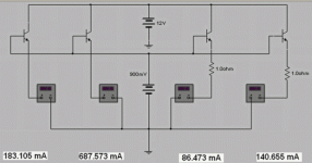
Then i have inserted amperometers in series with colector to emitter circuit.
Observe how currents are bigger...you see how bigger then are when not using emitter resistances...this is fine to audio power....the two transistors into the rigth side have emitter resistances..and they are limiting the power... some power will be developed over those emitter resistances.... you gonna have losses of power and heat.... where you have resistances you gonna have heat!...but observe the transistors are different.
Into those groups of two transistors.... 2 left hand transistors and 2 rigth hand transistors...the left one of those two groups are higher gain units...you see how bigger is the current because the unit higher gain.... even using emitter resistances, the current difference will exist....because the gain...but you may be able to control the power.
Observe the current measurements into those transistors.
regards,
Carlos
Attachments
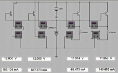
Now i will show you voltage and current informations
The voltage informed is the voltage you have measured from colector to emitter...so...it is connected directly to the power.... this voltage you can measure using DC voltimeter...one probe point at colector and the other at emitter... VCE is the name... Voltage from Colector to Emitter.
Also each current is informed.
You can see there are differences in current, even into the rigth hand.... those 2 transistors, even having emitter resistances shows current differences.
BUT!...... power is the result of the multiplication of Voltage by Current and them we gonna see different sittuations.
Observe the measurements.
regards,
Carlos
Attachments
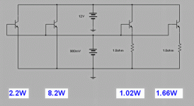
Now you can see the reason to use emitter resistances
You can see the power.... power differences into each transistor is less problematic into the rigth hand pair of transistors...
The difference of current into the ones have no emitter resistance is enormous..also the power difference as you can see into the sketch provided below.
The power was divided between the transistor Colector to Emitter junction and the resistance... the bigger the current flowing the smaller would be the transistor's Colector to Emitter voltage... and the consequence is that you gonna have smaller power... the bigger the current, the smaller the power into the transistor...the resistance will help a lot!
The dumping is disturbed with the emitter resistance presence...the bass is disturbed a lot.... kills the quality.... a sonic murderer....BUT, as transistors are different...we HAVE to use them when you are using more than one pair of transistors...and this...to turn power EQUAL into the power transistors.
I hope i have helped the ones had not this knowledge..there are many folks that does not know that.
regards,
Carlos
Attachments
carlos ...i am
very familiar with allthis and the math ...and the use of those resistors .....
but why 1ohm ? every body else is using 0.18-0.47 ....
this will take away some of your power and then will also produce more heat and finally will not add any stability more ....
also i think that reduces the idle ..... and so on
i presume that if you run this amp in 220w for 2-3 hours these resitors are going to be boiling
So, do not use 1 ohm....
...because what you presume.
The amplifier is not open to project discussion, already made, finished and tested.
If you think different, then apply your knowledge and be happy.
There's a lot of "others" in my place that uses rouge, batton and love to kiss other males into their lips... i have nothing to follow what "others" do.
Do not come with presumptions or assumptions..hold the soldering iron, remove it from the black hole you use it (the soldering iron support..hehehehe) and make this amplifier..then come to say it will be hot, cold, shinny, nice or awfull...but do it greek warrior.
ahahahahha!
Carlos
Attachments
Yess.. do it...build it...but in a different way refered to your
ancient Doctor Bora situation.
Make it following the schematic, the correct voltage, big heatsinks and do not inject power square wave into the input.
Or if you do that...please, do not have spectations the unit will survive to that kind of assassination.
Well...i tried to kill it here...but you are "The greek warrior"...you can kill it better.
You may say:
"Hasta la vista baby!".... and alike Schwatznegger, you may pull the trigger.
lice...nice....well.... it is a matter to type correctly or not!
ahahahahah!
Carlos
Attachments

carlos
dont get pissed off its just a question ....
you know i respect you and i like your designs very much ...the truth is that me and probably others want learn WHY ????? why the resistor why the transistor why this and why that
thats it nothing else ....every time we see something diferent we need to know why ...its only human
I do not want to let you know that a friend
arrived here and gave me a hundred of 1 ohm (3 watts) beautifull resistances.
Ahahahahaha!.... our secret... do not let folks know that!
that's the main reason.... the second one is because i have tested and had no problems.
I am sorry, sometimes i over react... behaving alike a Catterpillar..... maybe because i am a little bit "Greek" too.
Happens, and very often, that things are simple and does not carry "high technological reasons"... also i am not a "high technological man".
I am still learning things about audio.... and very happy to have things to learn.
Maybe smaller resistances will be better... give it a try Sakis!
regards,
Carlos
Attachments

Hi Carlos, from my class A experiments, I think Sakis, is giving attention to something worthwile...
I am reasonably sure it has no sonic impact, appart from a little power loss.
A 1ohm resistor will get twice as hot as say a .47R, I am sure it will survive medium and short term testing, but it may not be bad for an amp like this for long term survivability (new word?).
I hate those resistors burned into the PCB look you get on some gear that ran for some time.
I see you alleardy improved the "hot" resistor above the input pair, by spreading the resistances more equaly there, compared to the first version.
Was tested...works fine..will not be changed.
But i thank you all by the kind cooperation.
Of course, if you will build, or even Sakis... the problem is yours, because amplifier built will be yours..so...do the way you want..it is up to you.
Hate resistance?, then reduce it or even remove it..or put a bigger watt one...up to you.
regards,
Carlos
Too much worries..better not to spend time with worries and build something
Into the worst condition...2 ohms loads, full unclipped continuous power, we gonna have 7.9 amperes to each rail...and this will be divided to 5 resistances... each transistor emitter resistance will hold 1.5 watts (more or less this value..aprox.).
Those resistances are 3 to 5 watts...so....they are twice or three times bigger than the needed value.
Also....brazilian resistances, the 3 watts resistance dissipates 3 watts without turn too much hotter than the environment temperature.... are you using resistances or heaters in your amplifiers?.... resistances that goes hot are heaters!
I cannot understand those worries.... this is not a constant current amplifier..this is not a class A amplifier...almost all the time you gonna have less than 250 miliwatts power into each emitter resistance..... 1.5 watts when full continuous power....nobody uses full continuous steady tone 1 Kilohertz or other frequency sinusoidal power...so.... relax and be happy.
And i was thinking i use to worry too much... if i compare myself with U2 i will be the most relaxed man in earth.
Was tested folks.... why to search for lices into someone that has not hair... will not find lices there!
regards,
Carlos
hi,
my own exp in practical:
at first i was thinking too but i have used both 1ohm and o.47 they both are fine. later finally i used 1ohms as carlos recomended. my amp is fine, nothing unusual heat. i am operating it often for 4 to 6 hrs. nothing unusual heat. i feel fine
with 1 ohms.
chears carlos.......
😀
Thank you... this is what i have found here in my home
And for sure everybody will face this same reality.
regards,
Carlos
And for sure everybody will face this same reality.
regards,
Carlos
Another PCB for DHR-DX amplifier
...Hi to all,
I'm happy to present another variant for PCB 🙂http://i35.tinypic.com/actum9.jpg , 😀 please comment what is wrong this time .Regards alex mm
...Hi to all,
I'm happy to present another variant for PCB 🙂http://i35.tinypic.com/actum9.jpg , 😀 please comment what is wrong this time .Regards alex mm
.....error at the voltage rail
.... sorry folks I find something , polarity must be reversed at voltage rail , 😉 like this http://i37.tinypic.com/25fnj0k.jpg . all the best alex mm 😀
.... sorry folks I find something , polarity must be reversed at voltage rail , 😉 like this http://i37.tinypic.com/25fnj0k.jpg . all the best alex mm 😀
Alex,
the 1943/5200 has a poor SOAR at high voltage. For +-70Vdc supply rails these are not the most reliable devices.
eg 7pair give 233W into 8ohm 60degree phase angle and just hit the 100mS SOA for Tc=55degC.
But, deliver 417W into 4ohms and at 60degree phase angle are dissipating almost double the instantaneous 100mS SOA (about 770Wpk @ 90Vce) for the same Tc=55degC.
4ohm 40degree phase angle just hits the 100mS 55degC SOA.
This 7pair will drive a 2r0 load for as long as you can keep the Tc<=55degC (heatsink ~<40degC).
For all these predictions I used +-70Vdc from the 4% regulation transformer feeding +-15mF as a monoblock and Re=0r33.
I felt strange Alex.... too much busy today to watch it with carefull
But seems strange... the diodes, the heat sensor diodes, very important into this circuit...i am perceiving them under the board... well... i have to think about how to make them touch the heatsinks...maybe just bending... well... i will take a look latter.
My prefered solution, you could see into Space 2000 amplifier, is to use power transistors as heat sensors.
I am a hell busy today.
Thank you very much Alex.
regards,
Carlos
- Status
- Not open for further replies.
- Home
- Amplifiers
- Solid State
- This is the DHR.... Dx High Resolution Turbo